
eVSTOL: Tilt-Rotor Aircraft
Background and Motivation
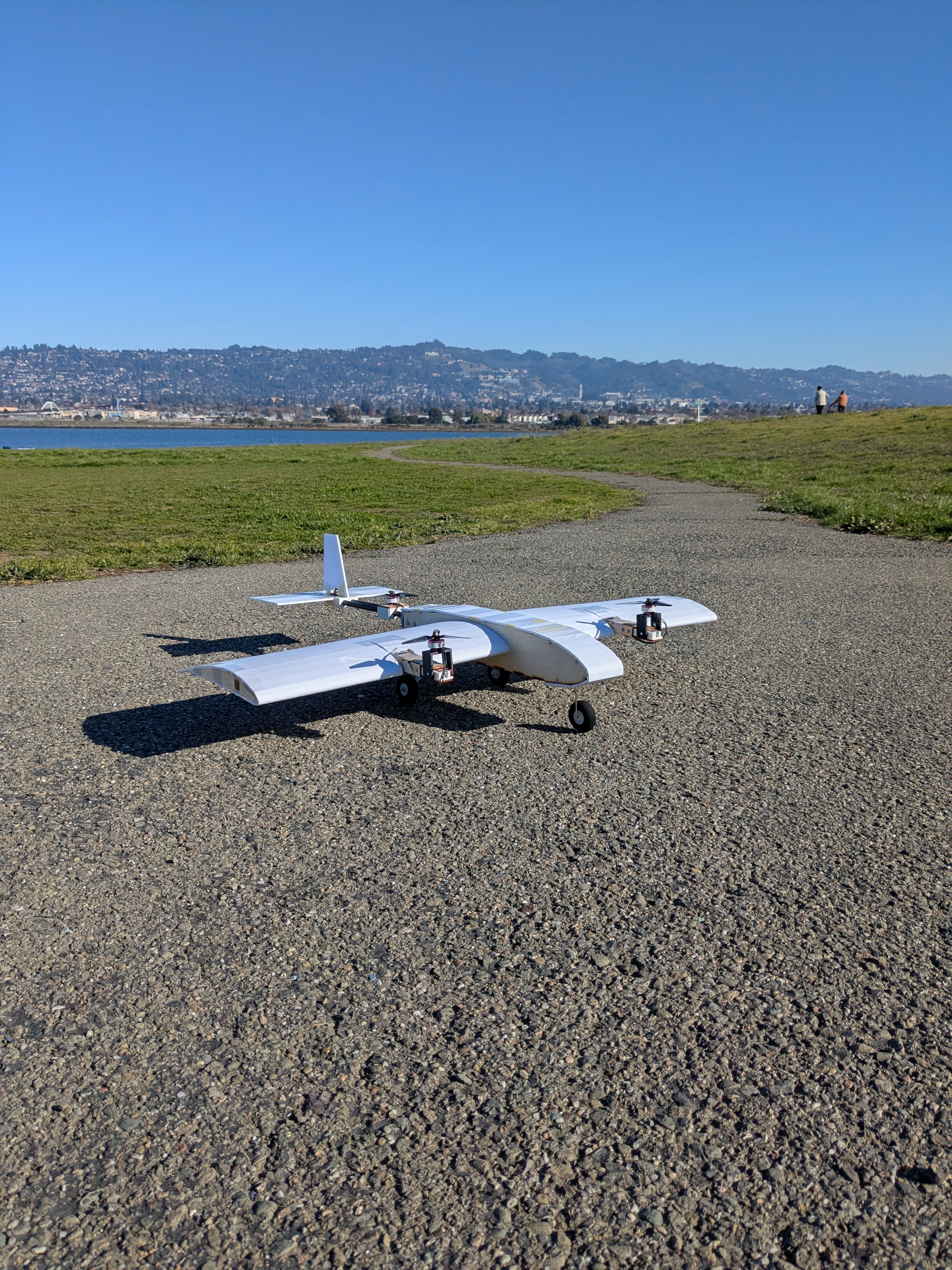
For ME 102B: Mechatronics Design at UC Berkeley, our team built an electric vertical / short take-off and landing (eVSTOL) aircraft. The goal was to combine the small takeoff footprint of a multirotor with the wing-supported flight of a conventional airplane.
Our design used three propellers: two wing-mounted motors that could tilt between vertical and forward thrust, and a fixed rear motor for vertical lift. An onboard flight computer combined radio commands with attitude feedback to drive the motors and servos.
We built the aircraft and developed its controls on a constrained test stand. The reported result was vertical-flight stability in two axes using proportional control. Transition to horizontal flight remained a development goal.
Contributors
- Ishaan Gupta
- Angel Hernandez
- Panithan Lertsuntivit
- Collin Shieh
My work focused on the ESP32 flight computer and embedded controls, integrating radio input, IMU feedback, and actuator commands.
Mechanical Design
Airframe and Tilting Propulsion
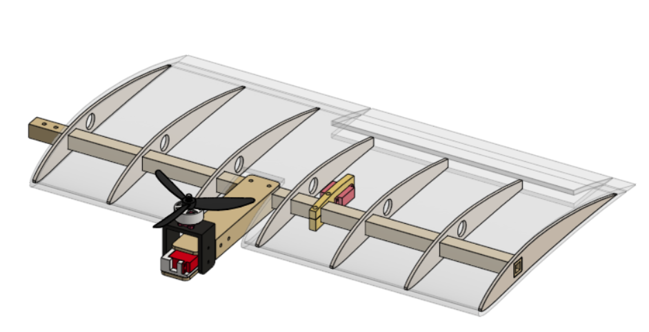
The airframe combined a plywood wing structure, ribs, foam-board surfaces, and a tail assembly. The front motors sat on servo-driven brackets, allowing their thrust direction to rotate between hover and forward-flight configurations. The rear propeller remained fixed for vertical lift.
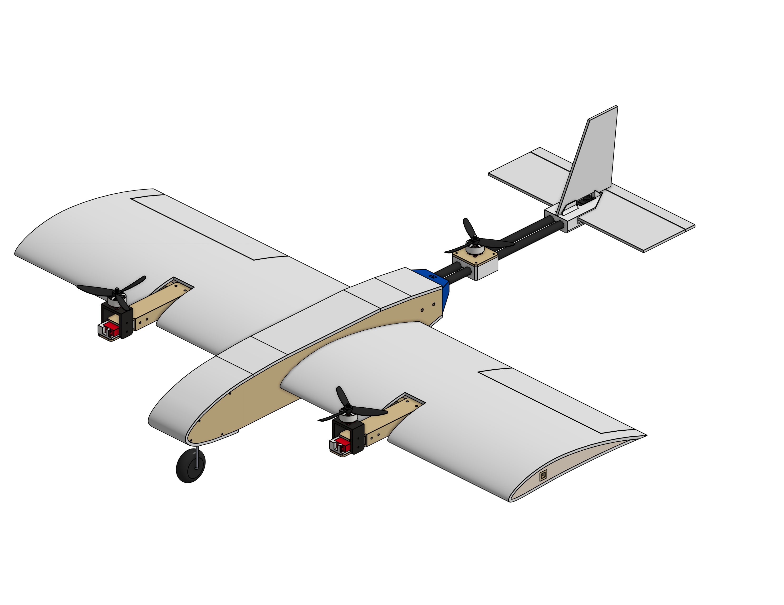
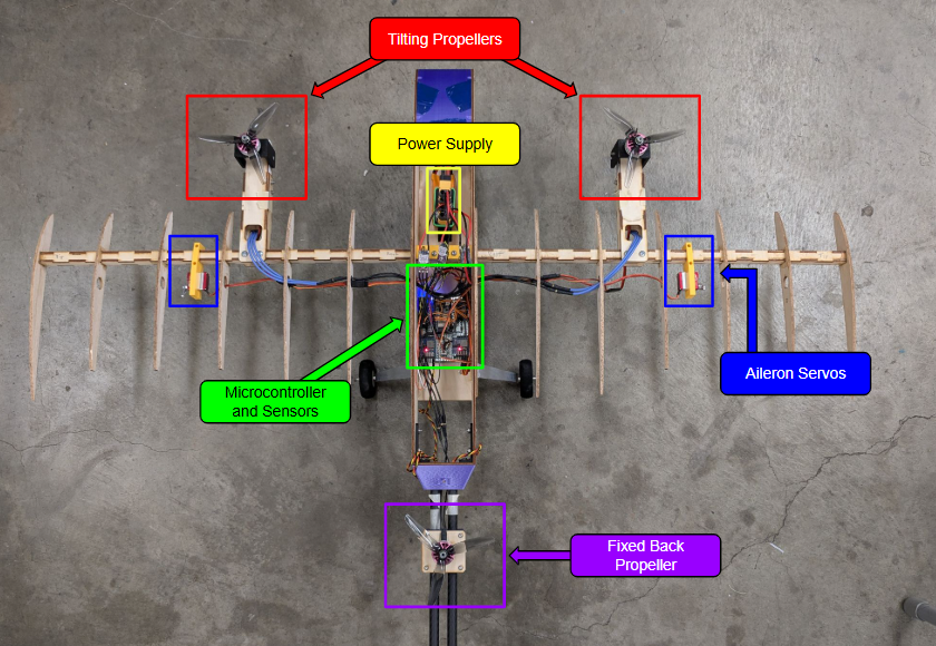
This arrangement required two ways of controlling attitude. In hover, changes in motor thrust and motor tilt generate moments. In forward flight, the ailerons and elevator become the primary roll and pitch actuators. The controller therefore needed a different actuator mixer for each operating mode.
Wing Spar Calculations
We checked the wing spar under two design load cases: a 2g maneuver in horizontal flight and full-throttle vertical lift. The analysis modeled the spar as an Euler–Bernoulli beam with an elliptical wing-load distribution. Its slenderness ratio was approximately 72, and the assumed aircraft weight was about 4 lb (18 N).
The beam-deflection and bending-stress equations used in the report were:
\[\frac{d^2}{dx^2}\left(EI\frac{d^2v}{dx^2}\right)=q(x),\qquad \sigma_{b,\max}=\frac{M_x c}{I_{xx}}\]Here, \(E\) is Young’s modulus, \(I\) the second moment of area, \(v\) deflection, and \(q(x)\) distributed load. The bending-stress expression uses the maximum moment \(M_x\) and distance \(c\) to the outermost fiber.
| Design load case | Calculated result |
|---|---|
| 2g horizontal-flight loading | Approximately 6 mm deflection |
| 2g horizontal-flight loading | 7.0 MPa maximum bending stress |
| Full-throttle vertical lift | 2.8 MPa maximum bending stress |
| Full-throttle vertical lift | 1.75 MPa maximum torsional shear stress |
The report compared these stresses with cited birch-plywood strengths of 60.0 MPa in tension and 12.8 MPa in shear. These were design calculations based on assumptions about material behavior and sufficiently strong glue joints, rather than measured flight loads.
Flight Computer and Electronics
The flight computer used an Adafruit ESP32 Feather V2 and an MPU9250 nine-axis IMU. Radio commands arrived through a TBS Crossfire Nano receiver, while the IMU connected over SPI with an interrupt signal for sensor updates.
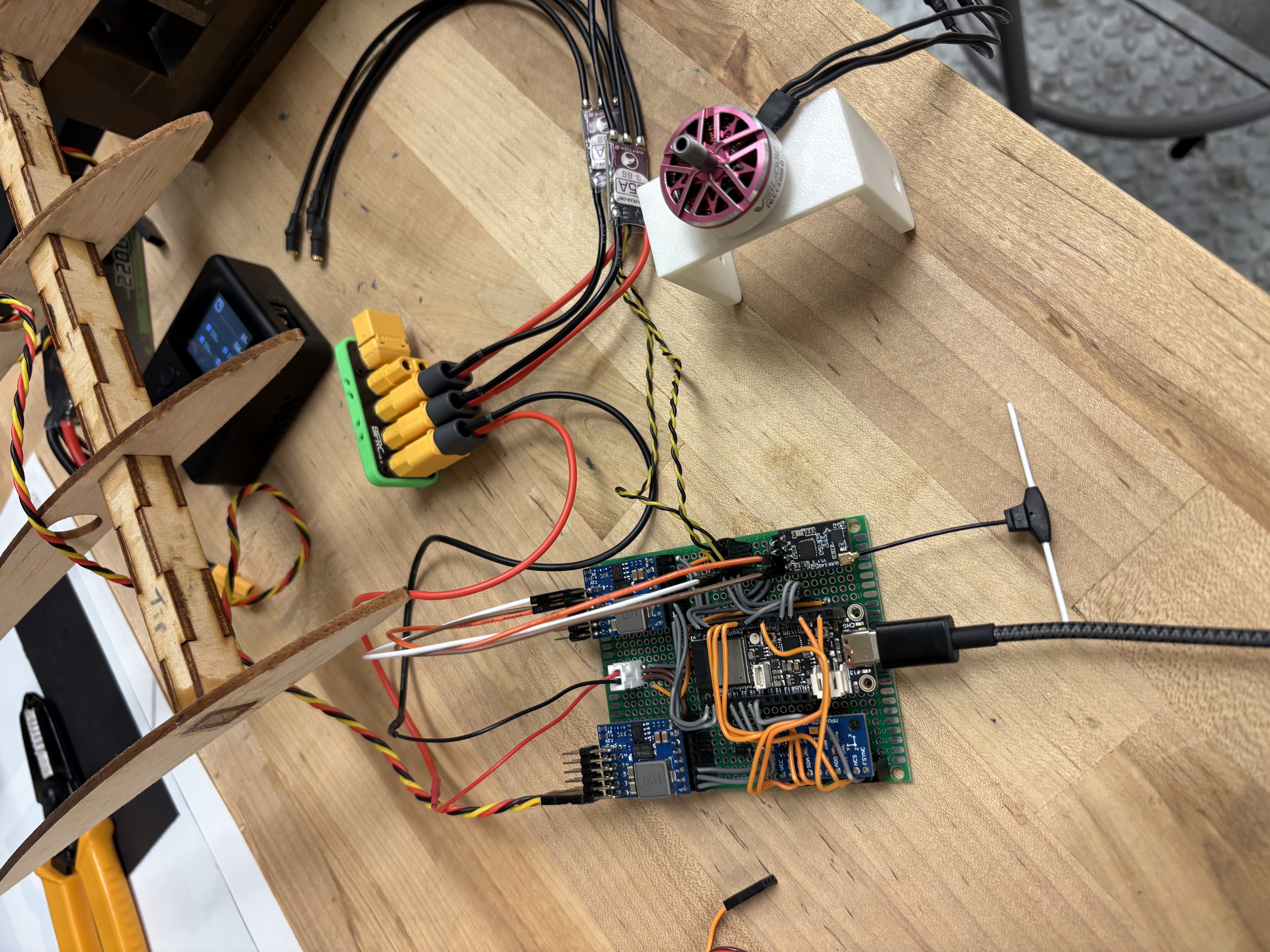
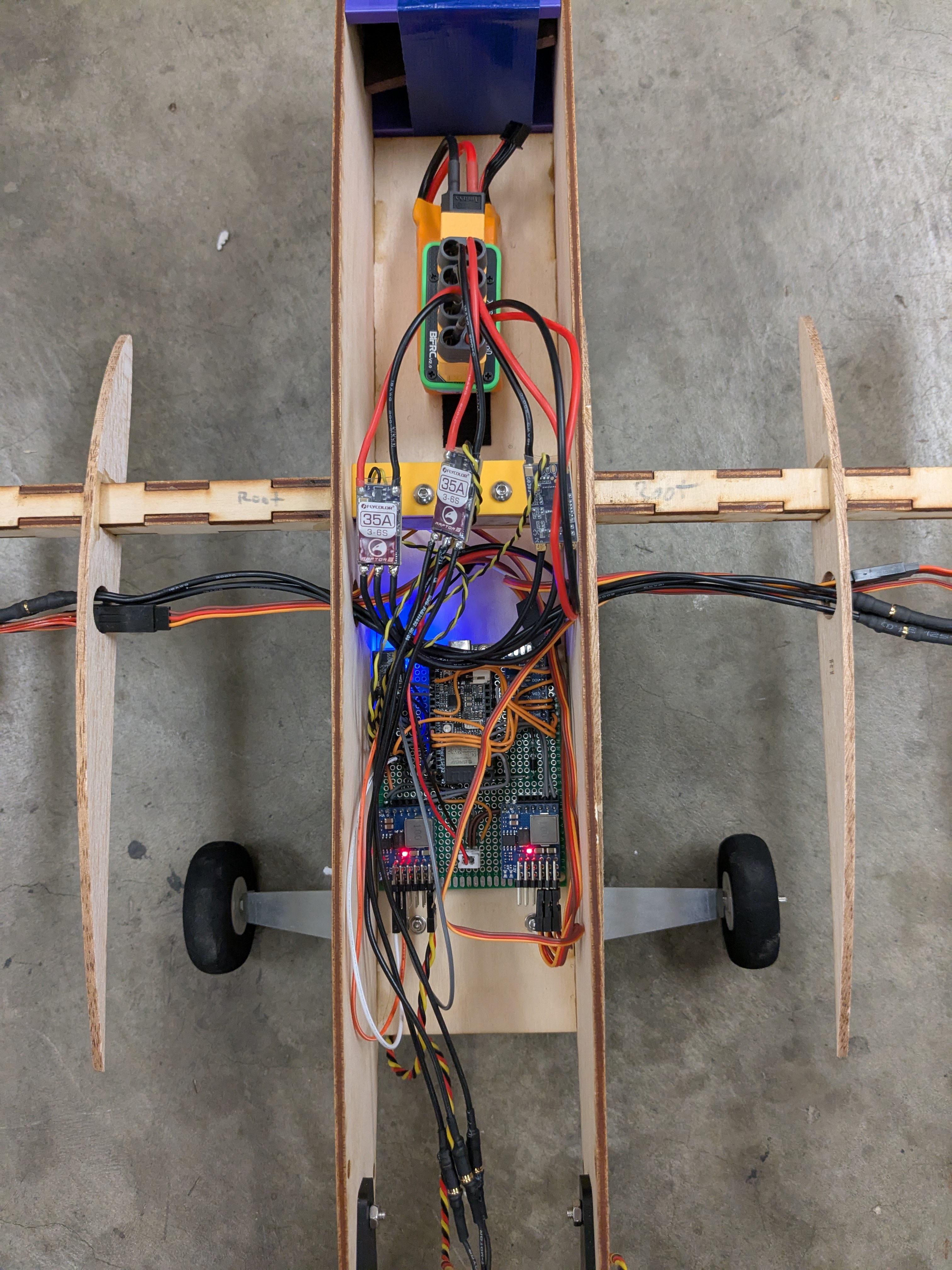
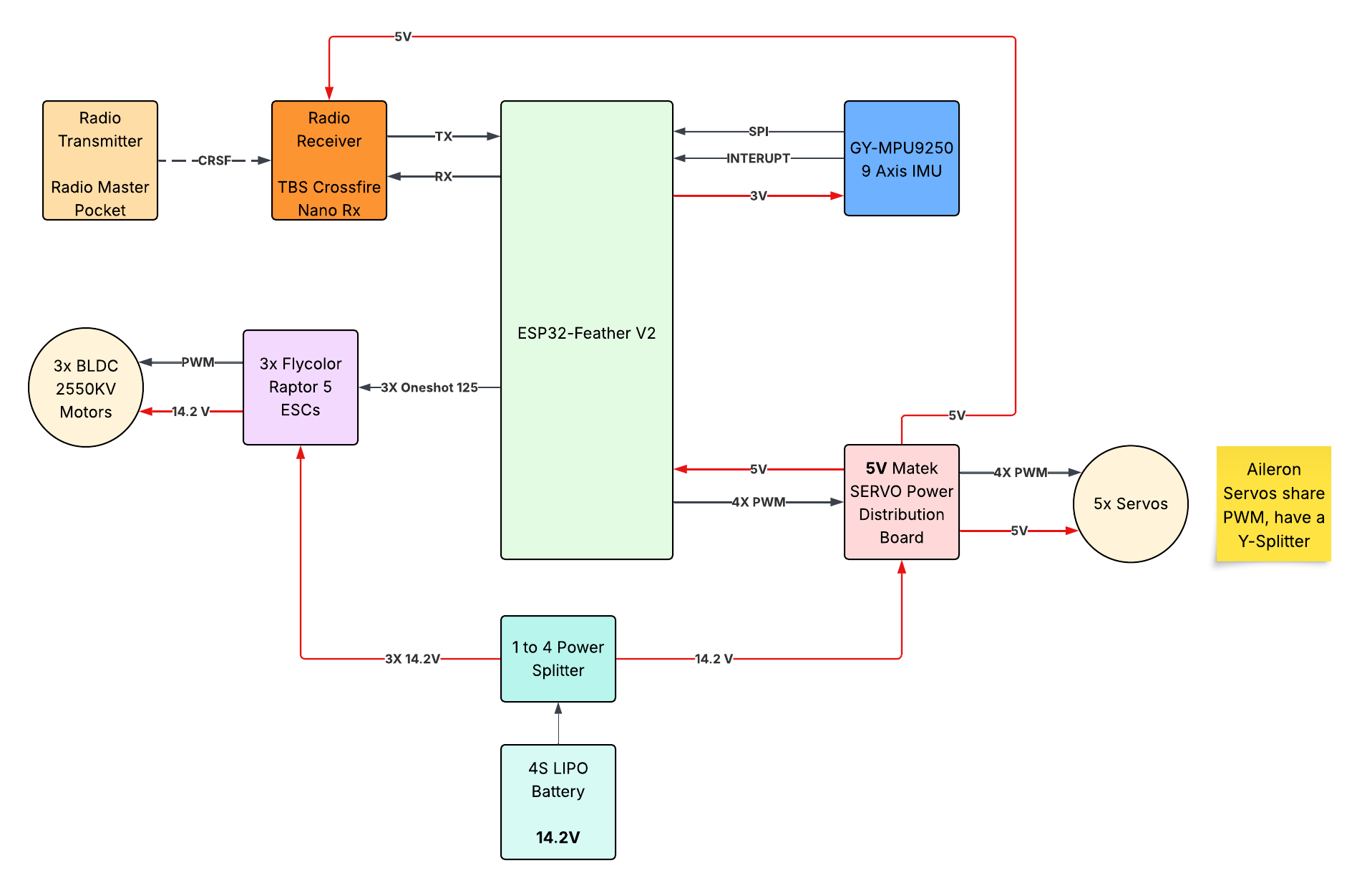
The propulsion system used three brushless motors and three ESCs, with OneShot125 commands from the flight computer. A 4S LiPo supplied the propulsion and a regulated servo power-distribution board. Five servos controlled the motor-tilt mechanisms and aerodynamic control surfaces; the two aileron servos shared a command through a Y-splitter.
Embedded Control
Attitude Estimation and Feedback
The firmware was built on the madflight Arduino flight-control library, with custom configuration and actuator mixing for this aircraft. A Mahony attitude estimator processed IMU measurements to provide the attitude feedback used by the controller.
Radio stick inputs established roll and pitch angle targets and a yaw-rate target. The firmware included proportional, integral, and derivative terms, integrator limits, and an integrator reset at minimum throttle. In the reported hover testing, the roll and pitch angle controllers used proportional gains of 0.30 and 0.45, with their integral and derivative gains set to zero.
For each controlled axis, the implemented structure was:
\[e_k=r_k-y_k,\qquad u_k=K_p e_k+K_i\sum e_k\Delta t+K_d\frac{e_k-e_{k-1}}{\Delta t}\]\(r_k\) is the commanded angle or rate, \(y_k\) its measured value, and \(u_k\) the correction passed to the actuator mixer. With zero integral and derivative gains, the tested angle-control law reduces to a proportional correction.
Flight Modes
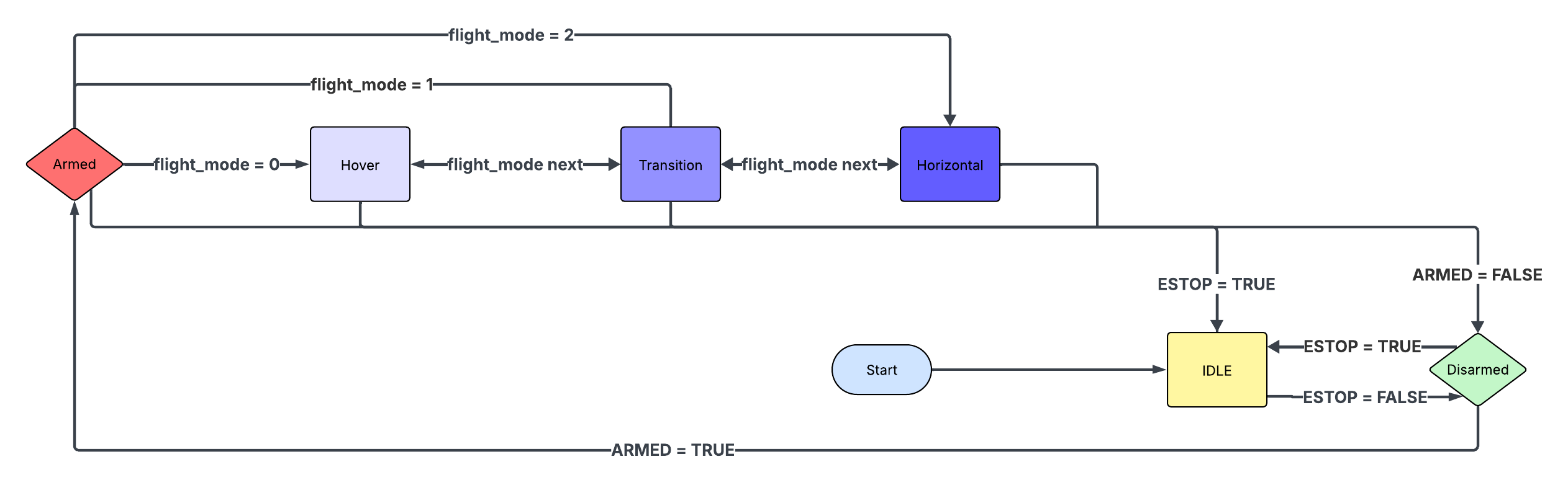
| Mode | Actuator behavior in the firmware |
|---|---|
| Hover | Three motors provide lift; thrust mixing controls roll and pitch, and differential front-motor tilt supplies yaw correction. |
| Transition | Front-motor tilt follows the radio pitch command, with test-specific motor-throttle scaling and centered control surfaces. |
| Horizontal | Front motors point forward, the rear motor stops, and radio commands drive aileron and elevator motion. |
The transition and horizontal mixers represented intended operating modes in the firmware. Their presence did not establish a successfully demonstrated hover-to-forward-flight transition.
Hover Mixing
The custom hover mixer combined a common throttle command with pitch and roll corrections. In the firmware’s motor ordering:
\[\begin{aligned} m_1 &= T+u_{\mathrm{pitch}}-u_{\mathrm{roll}}\\ m_2 &= T+u_{\mathrm{pitch}}+u_{\mathrm{roll}}\\ m_3 &= T-u_{\mathrm{pitch}} \end{aligned}\]The front motors receive equal pitch corrections and opposing roll corrections, while the rear motor receives the opposite pitch correction. Yaw corrections move the two front tilt-servo commands in opposite directions.
Servo updates were downsampled relative to the IMU loop so they would not slow the motor-control updates. The firmware also included motor arming logic and a radio-loss failsafe that disabled outputs when the vehicle was disarmed or the radio connection was lost.
Test Stand and Results
We built a test stand around a vertical rod, two linear bearings, and a ball joint attached to the fuselage. It permitted vertical translation and rotation about the aircraft’s roll, pitch, and yaw axes while constraining its overall motion.
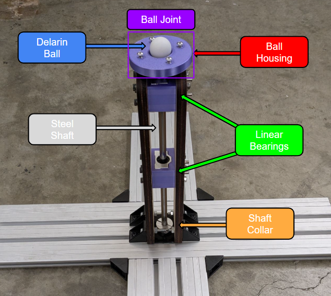
The stand let us investigate feedback behavior and tune the controller before attempting broader flight testing. The project achieved vertical-flight stability in two axes with proportional control. Full three-axis hover stabilization and transition to conventional horizontal flight were not established by the final report.
Lessons Learned
This project brought mechanical design, structural analysis, power distribution, sensor feedback, and real-time firmware into one system. The most useful control lesson was that an attitude controller must be paired with a mixer that reflects the actual actuator geometry and limits, especially when the thrust direction changes between modes.
Regular team work sessions, delegated tasks, and intermediate deadlines helped us integrate the aircraft. In a future iteration, we would seek experienced guidance earlier to improve the models and calculations used for design. Completing three-axis hover tuning and validating the transition behavior would be the next development steps.
Acknowledgments
Thanks to Dr. George Anwar for project guidance and access to the Hesse 50b lab, Chongdu Xu for help with testing and debugging, and Tom Clark for design insights and support during the aircraft showcase.