
Automatic Capper
Introduction
This project focused on developing an automated capper/decapper system for laboratory vials, building upon previous work on the cap dispenser project. The system was designed to interface with a UR-5 Robot Arm, which would introduce and remove sample caps from the system. The primary objectives were:
- Refining the cap dispenser design for improved reliability and full deployment into the A-Lab system
- Designing a new capper/decapper system from the ground up using an Ender 3 Pro as the base platform
- Developing a lab safety-compliant electrical system
- Sourcing and fabricating all necessary components
Design Considerations
- Cap Alignment
- Enable repeatable robot arm pick-ups and drop-offs
- Ensure consistent capper/decapper operations
- Operation Speed
- Improve upon existing capping/decapping speeds
- Complete capping/decapping in a single operation
- Manufacturing & Assembly
- 3D-printable body for rapid iteration
- Reduced part count for simplified assembly
- Reduced assembly time
- Platform Choice
- Ender 3 Pro base platform with open-source firmware for simple programming
- Rigid and reliable gantry to reduce design complexity
- Modularity
- Fast repairs and independent iteration of components
- System expandability for different volume requirements
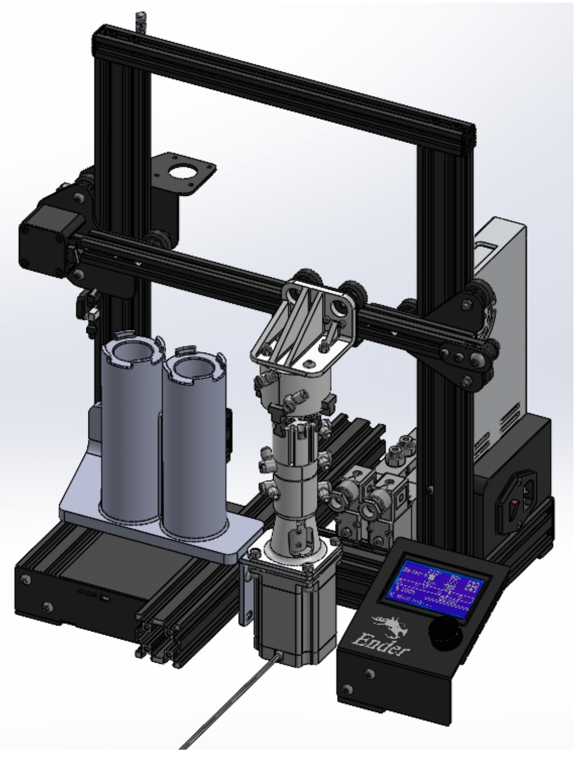
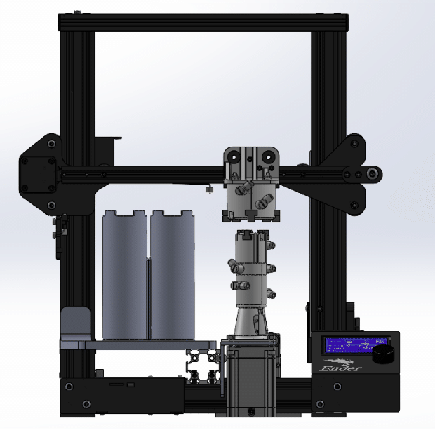
Mechanical System
Operation Process:
De-Capping Sequence:
- Upper gripper moves to home position
- Robot arm places sample on lower gripper, which clamps the vial
- Upper gripper clamps onto sample lid
- Stepper motor rotates vial while gantry raises upper gripper
- Sample unscrewed, lid placed on lid platform
Capping Sequence:
- Upper gripper retrieves lid from platform
- Stepper motor rotates vial while gantry lowers upper gripper
- Sample capped and retrieved by robot arm
Vial Gripper Assembly
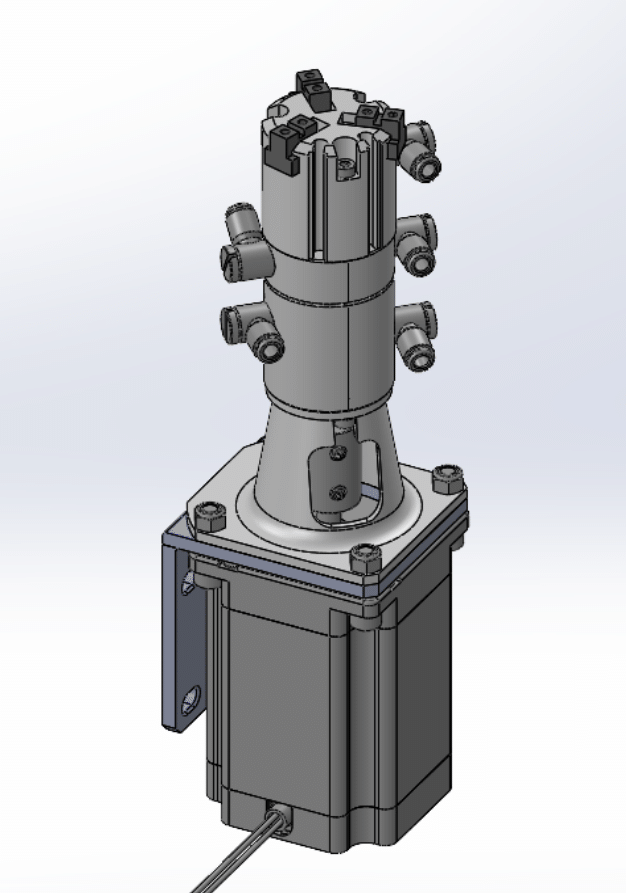
The assembly features:
- SMC Pneumatic Gripper
- Rotary Union for air transmission through rotating joint
- Nema 23 motor providing up to 2 N*m torque
- Custom-designed components for integration
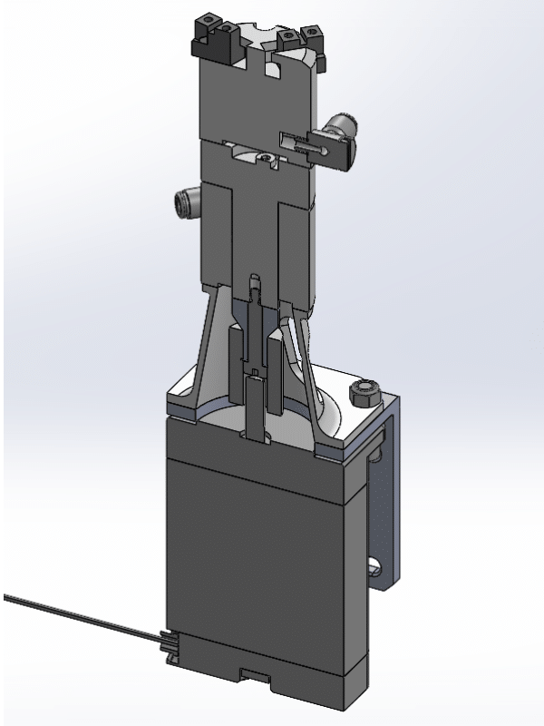
Custom Components
Rotary Union Extension
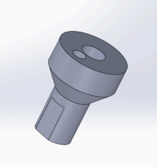
The Rotary Union Extension is attached to the Rotary Union by a shoulder bolt that passes through its center and threads into the Rotary Union. To constrain the 2 components rotationally, a pin is placed in the off center hole, and lines up with a similar hole on the Rotary Union itself. The power of the motor is transferred through the pin. This ensures that the shoulder bolt does not tighten and and loosen as the Stepper Motor turns clockwise and counterclockwise. Is currently 3-D printed, but should be machined out of steel to ensure longevity.
Rotary Union Mount
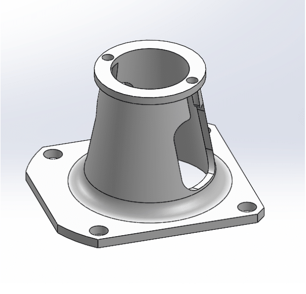
- Secures stationary half of Rotary Union
- Designed with access pockets for shaft coupler maintenance
Lid Platform
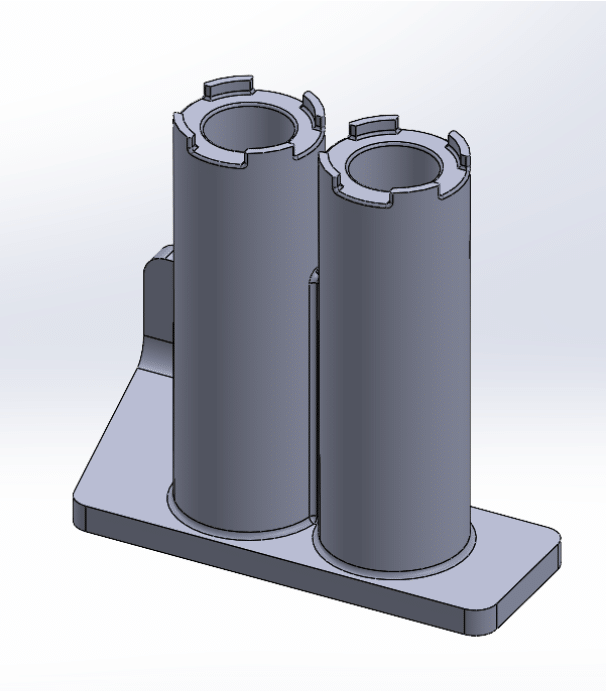
- Dual position design for removed and shaker lids
- Height-matched to Vial Gripper Assembly for optimized cycle times
Pneumatic System
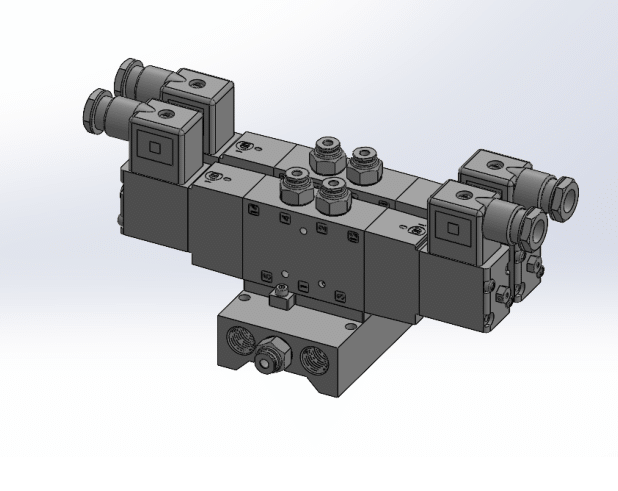
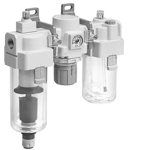
System flow:
- Wall air enters FRL filter for contaminant removal
- Regulator maintains pressure within SMC Gripper range (0.1 to 0.6 MPa)
- Lubricator adds oil particles for mechanical reliability
- Electric shut-off solenoid controls system air flow
- Manifold distributes air to 5/3 solenoids
- Exhaust flow control valves manage gripper operation speed
Electrical System
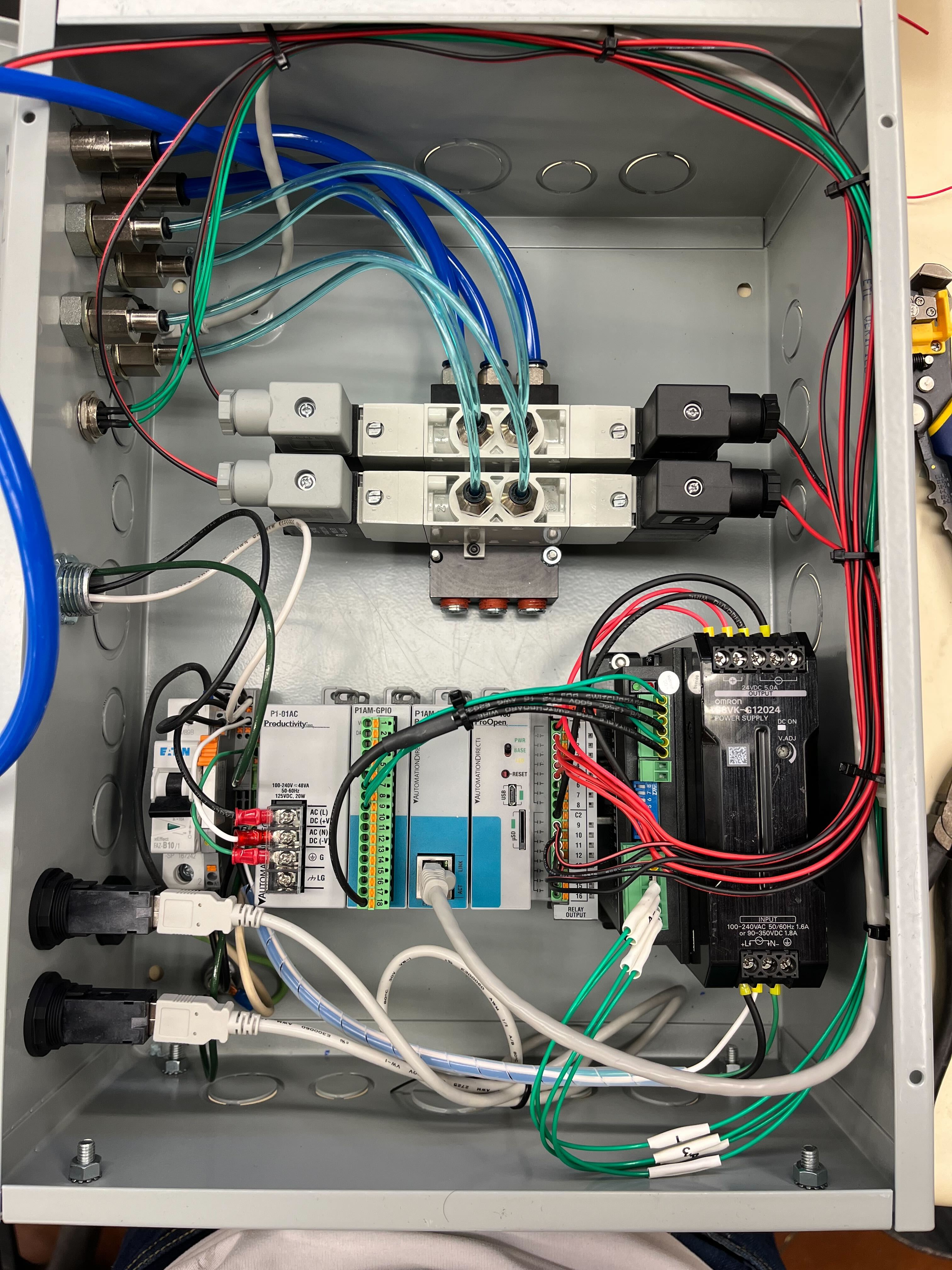
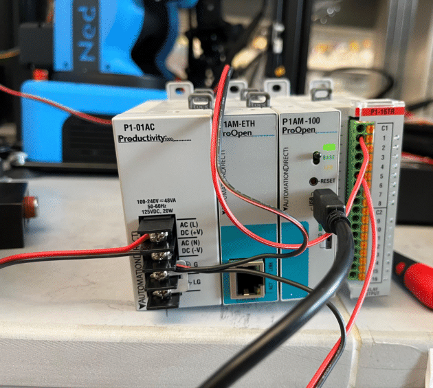
Key Features:
- Open-source solution using ProductiveOpen Controllers
- Arduino-based PLC system for enhanced maintainability
- DIN rail mounted components for safety compliance
- Remote control capability for Ender 3
-
- BIGTREETECH SKR MINI E3 V2 motherboard upgrade for advanced control via Klipper