
Echo: Robot Pen Plotter
Contributors
- Ishaan Gupta - FOC Firmware & PCB Design
- Charles Paxson - GUI Software and Firmware & PCB Design
- David Soto Gonzales - Mechanical Design
- Luz Torralba - Mechanical Design
Background/Motivation
The initial idea for this project was to have something with FOC, or “Field Oriented Control”, which we knew very little about, creating a challenge for ourselves to implement FOC. After going through many ideas, we decided on creating a pair of parallel SCARA robots for telepresence that would have an electromagnet end effector attached to a solenoid for pick-and-place tasks. More and more applications entail human-robot interactions, so we wanted to work on making them easier and safer to use. The system is in a similar vein as “steer-by-wire”, in that movements can be amplified, which could be useful for people with limited mobility/dexterity. However, as time went on, as we progressed with the project and challenges arose, we decided to replace the electromagnetic end effector with a pen mount for drawing/plotting.
System Overview
Our system is composed of 3 main elements:
- The motors (and accompanying motor controllers)
- The robot controller
- The computer
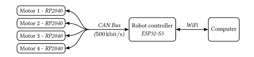
The RP2040 motor controllers connect over a single CAN bus to the ESP32 robot controller, which is itself connected wirelessly to a laptop.
Our initial plan was to have each robot use its own ESP32-S3 robot controller communicating via ESP-NOW, but decided to cut it down to one after seeing latency play such a huge role with our attempts at running haptic feedback.
Hardware
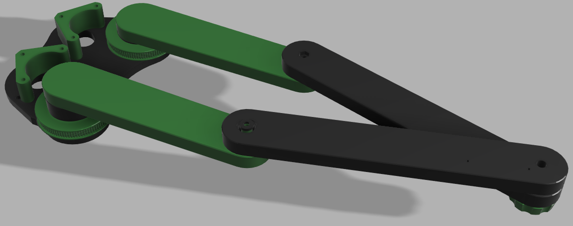
Robot Design
Designed in Fusion 360, the robot is a 2-axis parallel SCARA robot optimized for drawing. It has a reachable workspace that can fully enclose a sheet of letter paper.
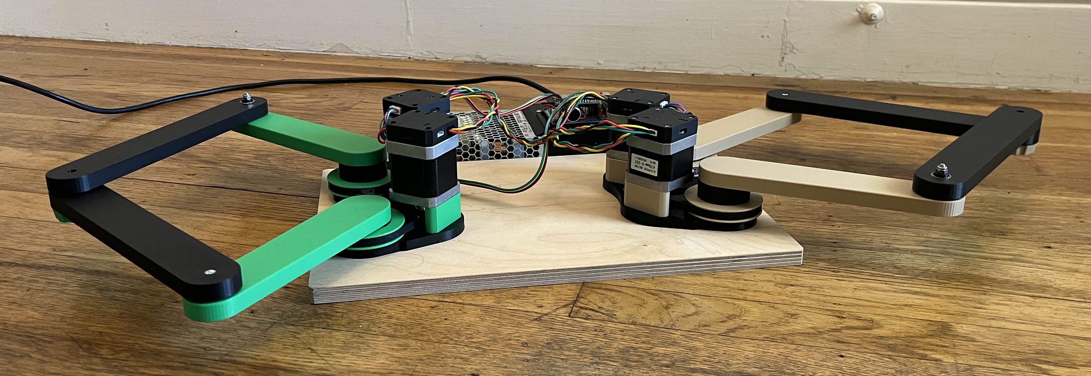
All of the major components were 3D printed for easy prototyping and testing. We used thrust bearings at the base of each arm for smooth rotation and small bearings on the elbow joints of each arm. Everything was kept together with the use of M3 & M4 nuts and bolts.
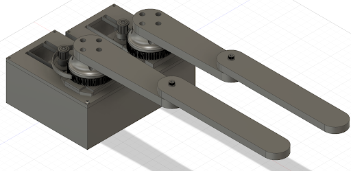
Our initial design was to create a basic prototype of the parallel SCARA robot with every major component and hardware needed to at least make it move.
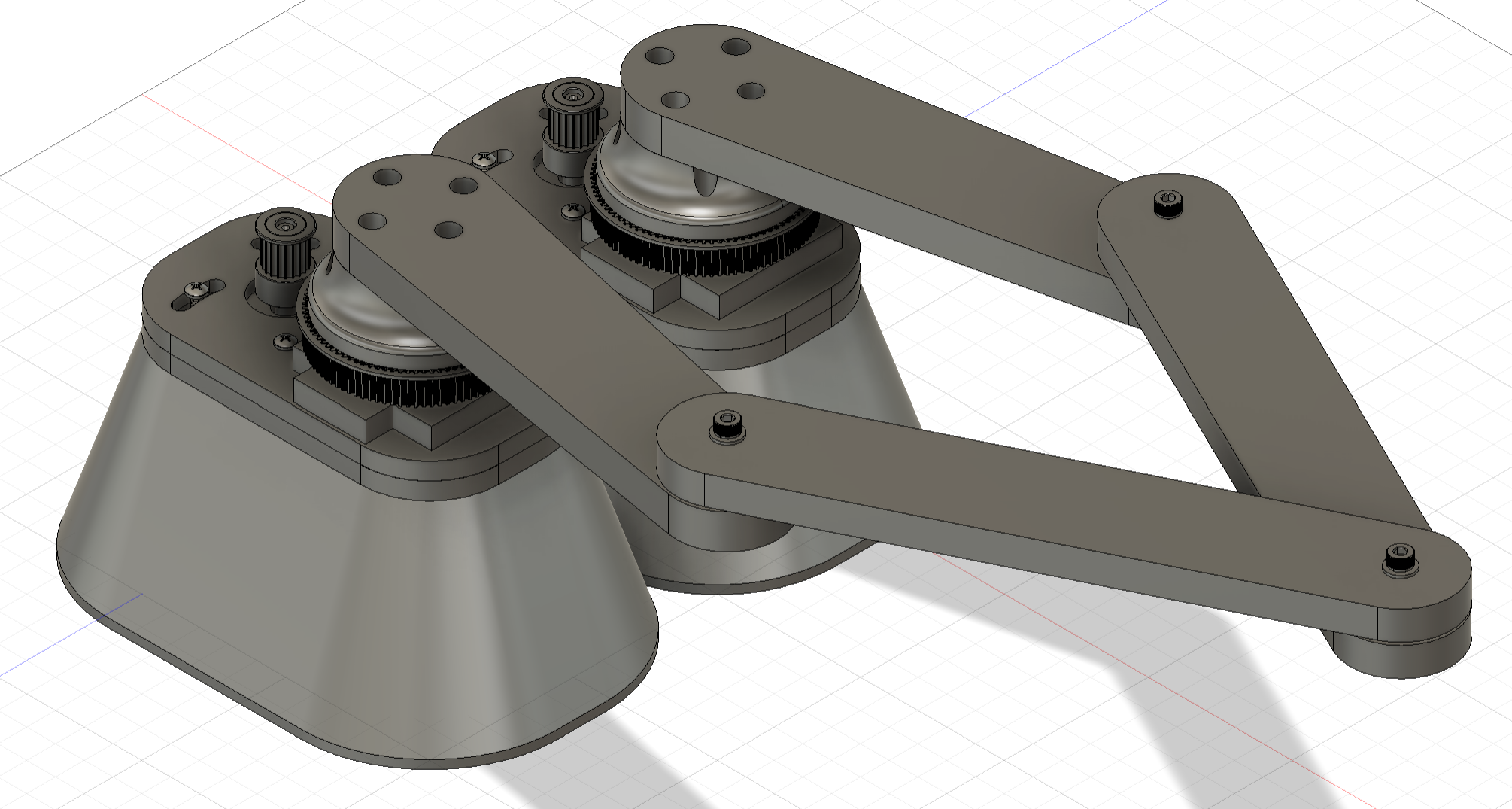
The second iteration made changes to the body to make it look more appealing, changed the arms’ lengths to cover a large area, and changed the way the motors were attached to the body to save on filament.
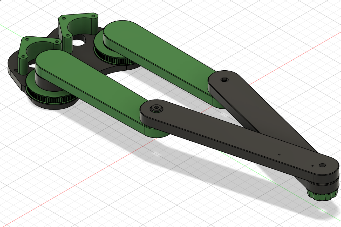
For our final iteration, when we decided to switch to mainly creating a drawing robot, we flipped the motors upside down to allow us to bring the arms closer to the ground level, while saving material.
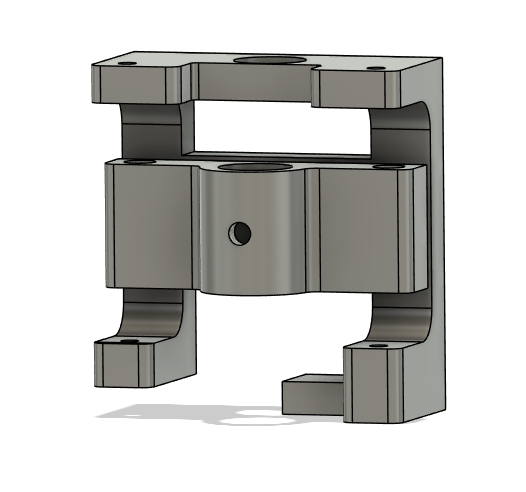
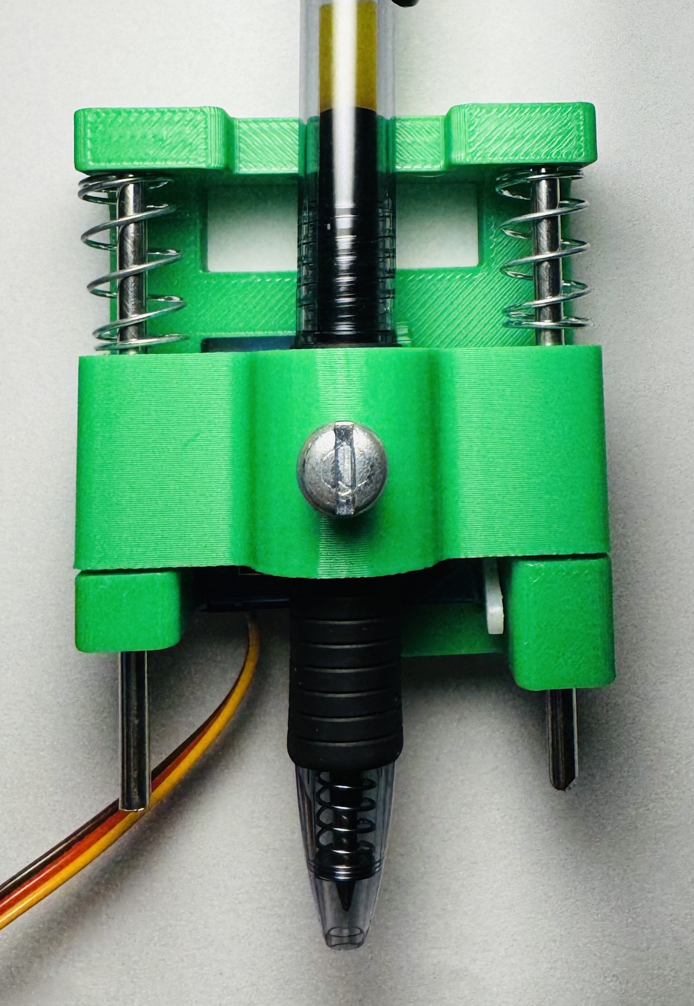
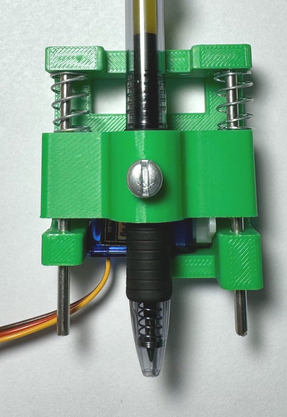
Pen Mount
The pen mount design focuses on maintaining smooth contact between the pen tip and the paper while providing the ability to lift the pen off the surface when necessary. The pen is housed within a spring-loaded 3mm steel rod that allows slight vertical movement. This compliant mechanism ensures consistent contact pressure on the paper, compensating for minor surface irregularities in the paper. A micro servo motor (SG90) is used to move the pen in the vertical direction. During writing, the spring-loaded mechanism gently presses the pen tip against the surface. When lifting is required, the servo rotates up, compressing the spring to ensure the pen does not touch the paper.
Motor Controller PCB
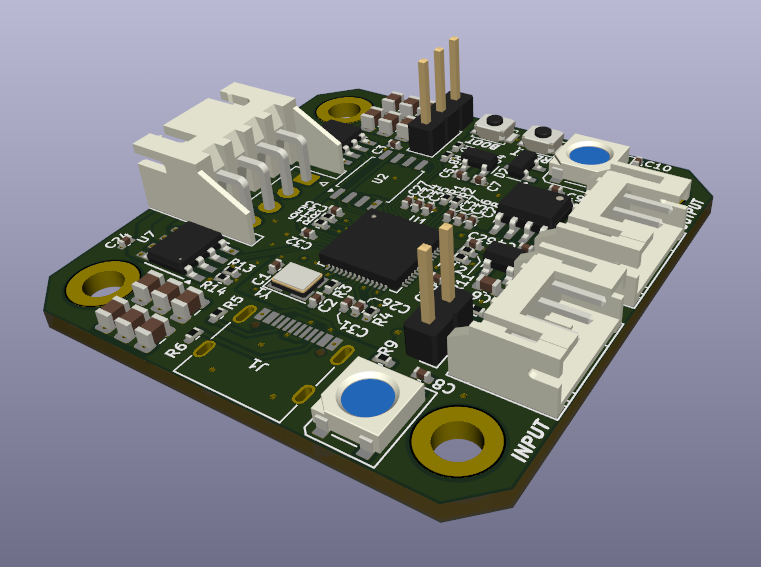
Our motor controller is a custom 6-layer PCB designed in KiCad with several key features:
- RP2040 (2-core ARM processor, 133 MHz)
- MT6701 14-bit magnetic encoder using I2C
- 2x DRV8251A 4.1A H-bridge motor driver with an integrated current sensor
- SN65HVD1050D CAN transceiver
- 2 input ports for daisy-chaining
- 48V input, 4A output
- Single-sided for easier assembly (except for the magnetic encoder)
We were designing this PCB with more than just this project in mind, as it can, in theory, turn any NEMA17 stepper motor into a powerful servo motor. Hence, it has power specs that are extremely overkill for this project, and realistically most NEMA17 stepper motors.
However, during bring-up, we found a couple major issues:
- Our VMOT → 5V LDO regulator was undersized, since we didn’t realize they dissipate power relative to their voltage drop. Thus at 24V input, we could not power the two NeoPixel indicator LEDs we added without USB power supplementing the LDO.
- We had an error in our magnetic encoder schematic, that pulled the MODE pin to ground and put the sensor into quadrature mode instead of I2C mode.
Robot Controller
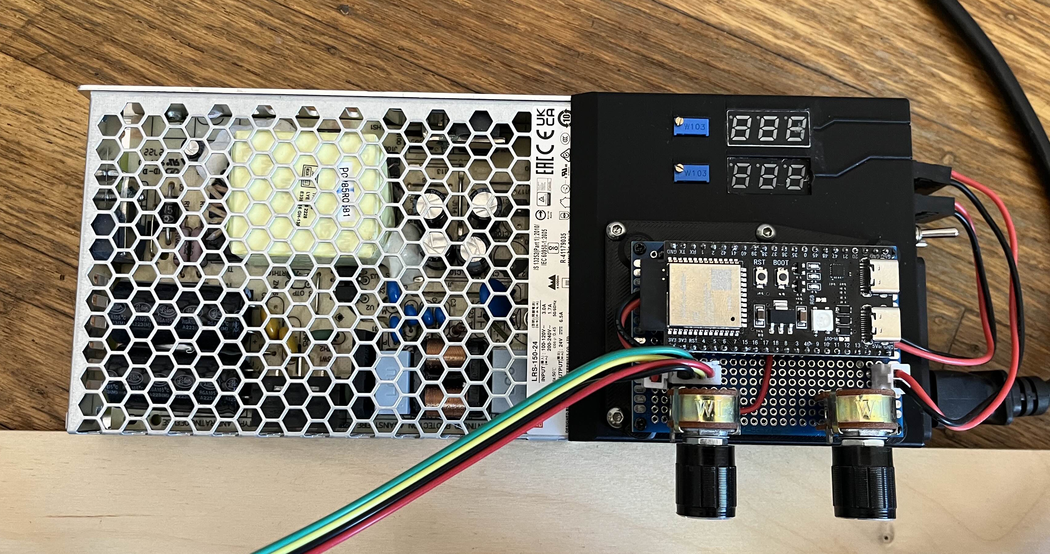
Our robot controller is basically an ESP32-S3 devkit mounted to a protoboard with a couple of potentiometers we used for testing, and a CAN transceiver. That board is then mounted to a little benchtop power supply box we created out of some voltage meters, a power supply, and buck converters.
Software
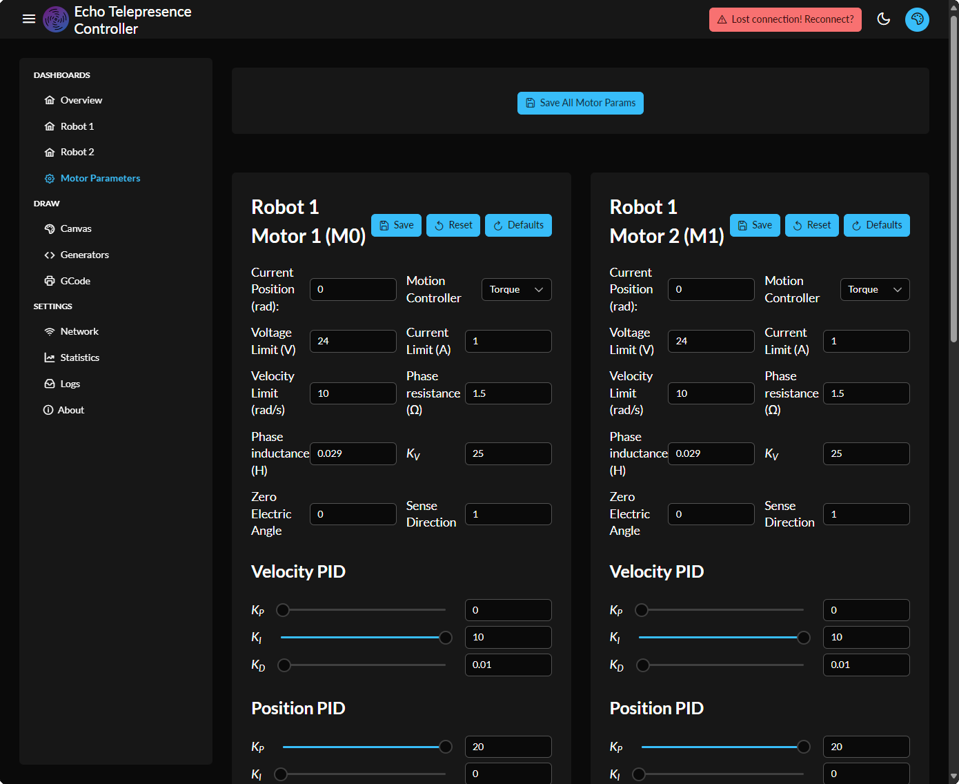
GUI
Our GUI is a web-based interface that allows the user to control the robot and view its status in real-time. It was developed with the Vue.js JavaScript framework, allowing elements to be reused and the code to be reactive between them.
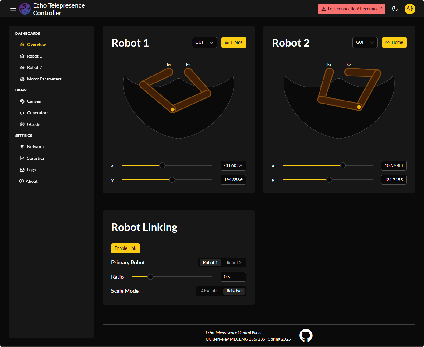
The GUI connects over a WebSocket to stream position data wirelessly both to and from the robot controller, and uses a REST API to send and request single-time data like motor parameters, motor status, and homing state.
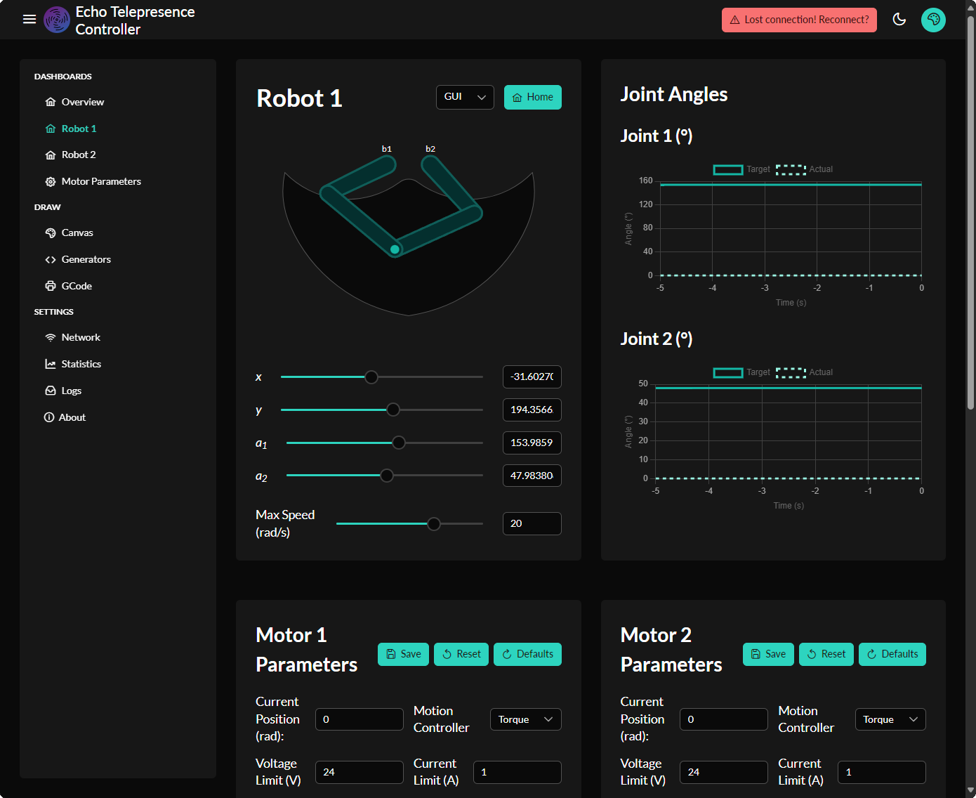
We implemented several pages:
- Dashboard
- Robot 1 Controls
- Robot 2 Controls
- Motor Parameters (all 4 motors, between both robots)
Embedded Systems
The system uses both an RP2040 for motor control and an ESP32 for robot control:
Motor Controller (RP2040)
Most of our real-time computation is performed directly on the 4 RP2040 motor controllers. This includes both a Field-Oriented Control (FOC) implementation and a CAN controller emulator. The RP2040 features two ARM Cortex-M0+ cores, which we leveraged to maximize performance:
- One core is fully dedicated to executing the FOC control loop at high frequency
- The second core handles all CAN transmit and receive operations
MT6701_I2C Implementation
This code implements an I²C interface driver for the MT6701 magnetic rotary encoder, allowing precise angle measurements to be read by a microcontroller. It supports initialization, raw angle register reads, angle conversion to radians, and I²C device scanning. The sensor is configured using resolution and bit-mapping parameters, and angle data is extracted from MSB/LSB registers via I²C. A built-in bus scan function can detect active I²C devices on the bus, useful for debugging sensor connectivity.
#include "MT6701_I2C.h"


/** Typical configuration for the 12bit MT6701 magnetic sensor over I2C interface */
MT6701_I2CConfig_s sensor_default = {
    .chip_address = 0x06,
    .bit_resolution = 14,
    .angle_register = 0x03,
    .data_start_bit = 15
};


// MagneticSensorI2C(uint8_t _chip_address, float _cpr, uint8_t _angle_register_msb)
//  @param _chip_address  I2C chip address
//  @param _bit_resolution  bit resolution of the sensor
//  @param _angle_register_msb  angle read register
//  @param _bits_used_msb number of used bits in msb
MT6701_I2C::MT6701_I2C(uint8_t _chip_address, int _bit_resolution, uint8_t _angle_register_msb, int _bits_used_msb){
    // chip I2C address
    chip_address = _chip_address;
    // angle read register of the magnetic sensor
    angle_register_msb = _angle_register_msb;
    // register maximum value (counts per revolution)
    cpr = _powtwo(_bit_resolution);

    // depending on the sensor architecture there are different combinations of
    // LSB and MSB register used bits
    // AS5600 uses 0..7 LSB and 8..11 MSB
    // AS5048 uses 0..5 LSB and 6..13 MSB
    // MT6701 uses 0..5 LSB and 9..15 MSB
    // used bits in LSB
    lsb_used = _bit_resolution - _bits_used_msb;
    // extraction masks
    lsb_mask = (uint8_t)( (2 << lsb_used) - 1 );
    msb_mask = (uint8_t)( (2 << _bits_used_msb) - 1 );
}

MT6701_I2C::MT6701_I2C(MT6701_I2CConfig_s config){
    chip_address = config.chip_address;

    // angle read register of the magnetic sensor
    angle_register_msb = config.angle_register;
    // register maximum value (counts per revolution)
    cpr = _powtwo(config.bit_resolution);

    int bits_used_msb = config.data_start_bit - 7;
    lsb_used = config.bit_resolution - bits_used_msb;
    // extraction masks
    lsb_mask = (uint8_t)( (2 << lsb_used) - 1 );
    msb_mask = (uint8_t)( (2 << bits_used_msb) - 1 );
}


void MT6701_I2C::init(i2c_inst_t* i2c_port, uint8_t sda_pin, uint8_t scl_pin) {
    I2C_PORT = i2c_port;
    I2C_SCL_PIN = scl_pin;
    I2C_SDA_PIN = sda_pin;

    i2c_init(I2C_PORT, 400 * 1000);  // Initialize I2C with 100kHz clock

    gpio_set_function(I2C_SDA_PIN, GPIO_FUNC_I2C);
    gpio_set_function(I2C_SCL_PIN, GPIO_FUNC_I2C);

    gpio_pull_up(I2C_SDA_PIN);
    gpio_pull_up(I2C_SCL_PIN);

    this->Sensor::init(); // call base class init
}

//  Shaft angle calculation
//  angle is in radians [rad]
float MT6701_I2C::getSensorAngle(){
    // (number of full rotations)*2PI + current sensor angle
    return  ( getRawCount() / (float)cpr) * _2PI ;
}


// function reading the raw counter of the magnetic sensor
int MT6701_I2C::getRawCount(){
	return (int)MT6701_I2C::read(angle_register_msb);
}

// I2C functions
/*
* Read a register from the sensor
* Takes the address of the register as a uint8_t
* Returns the value of the register
*/
int MT6701_I2C::read(uint8_t angle_reg_msb) {
    // read the angle register first MSB then LSB
    uint8_t readArray[2];
    uint16_t readValue = 0;

    // MT6701 uses 0..5 LSB and 6..13 MSB
    // Read data from register(s) over I2C
    i2c_write_blocking(I2C_PORT, chip_address, &angle_register_msb, 1, true);
    i2c_read_blocking(I2C_PORT, chip_address, readArray, 2, false);

    // Data is split between 8 bits in Reg 0x03 and 6 bits in Reg 0x04
    readValue = ((readArray[0] << 8) | (readArray[1])) >> 2;

    return readValue;
}

// Sweep through all 7-bit I2C addresses, to see if any slaves are present on
// the I2C bus. Print out a table that looks like this:
//
// I2C Bus Scan
//    0 1 2 3 4 5 6 7 8 9 A B C D E F
// 00 . . . . . . . . . . . . . . . .
// 10 . . @ . . . . . . . . . . . . .
// 20 . . . . . . . . . . . . . . . .
// 30 . . . . @ . . . . . . . . . . .
// 40 . . . . . . . . . . . . . . . .
// 50 . . . . . . . . . . . . . . . .
// 60 . . . . . . . . . . . . . . . .
// 70 . . . . . . . . . . . . . . . .
// E.g. if addresses 0x12 and 0x34 were acknowledged.

// I2C reserves some addresses for special purposes. We exclude these from the scan.
// These are any addresses of the form 000 0xxx or 111 1xxx
bool reserved_addr(uint8_t addr) {
    return (addr & 0x78) == 0 || (addr & 0x78) == 0x78;
}

void MT6701_I2C::i2c_scan() {

    printf("\nI2C Bus Scan\n");
    printf("   0  1  2  3  4  5  6  7  8  9  A  B  C  D  E  F\n");

    for (int addr = 0; addr < (1 << 7); ++addr) {
        if (addr % 16 == 0) {
            printf("%02x ", addr);
        }

        // Perform a 1-byte dummy read from the probe address. If a slave
        // acknowledges this address, the function returns the number of bytes
        // transferred. If the address byte is ignored, the function returns
        // -1.

        // Skip over any reserved addresses.
        int ret;
        uint8_t rxdata;

        //MT6701 DOES NOT follow i2c reserved address specs, reserved address condition ignored
        // if (reserved_addr(addr))
        //     ret = PICO_ERROR_GENERIC;
        // else
            ret = i2c_read_blocking(I2C_PORT, addr, &rxdata, 1, false);

        printf(ret < 0 ? "." : "@");
        printf(addr % 16 == 15 ? "\n" : "  ");
    }
    printf("Done.\n");
}
Core0 Main Implementation
The main function initializes the motor control system and continuously runs the Field-Oriented Control (FOC) loop. It sets up standard I/O, launches the CAN communication handler on Core 1, and waits for configuration data over CAN before proceeding.
int main() {
    stdio_init_all();
    sleep_ms(10000);

    printf("Entered core0 (core=%d)\n", get_core_num());
    multicore_launch_core1(core1_main);

    // Wait for the CAN RX notify flag
    while (!( received_can)) {
        printf("Waiting for CAN RX notify...\n");
        tight_loop_contents(); // Wait in a tight loop
    }
    printf("Start... \n");

    sensor.init(I2C_PORT, I2C_SCL_PIN, I2C_SDA_PIN); // Initialize the MT6701_I2C instance
    // link the motor to the sensor
    motor.linkSensor(&sensor);

    driver.voltage_power_supply = 24; // set the power supply voltage for the driver
    driver.voltage_limit = 24; // set the voltage limit for the driver
    // driver config
    driver.init();
    motor.linkDriver(&driver);

    motor.PID_velocity.P = 0.2;
    motor.PID_velocity.I = 20;
    motor.PID_velocity.D = 0.001;

    motor.PID_velocity.output_ramp = 1000; // Set the output ramp for the velocity PID controller

    motor.LPF_velocity.Tf = 0.005;

    motor.P_angle.P = 20;
    motor.P_angle.I = 0;
    motor.P_angle.D = 0;

    motor.P_angle.output_ramp = 10000; // default 1e6 rad/s^2
    motor.LPF_angle.Tf = 0; // default 0

    motor.velocity_limit = vel_Lim; // Set the position limit

    // set motion control loop to be used
    // default voltage_power_supply
    motor.voltage_limit = V_lim; // Volts
    motor.phase_resistance = R; // Ohm
    motor.phase_inductance = L; // Henry
    motor.KV_rating = kV; // V/rad/s
    motor.current_limit = I_lim; // Amps

    motor.voltage_sensor_align = 14;

    // Determine the controller type
    switch (controller) {
        case 0: //Disabled
            motor.controller = MotionControlType::torque;
            motor.torque_controller = TorqueControlType::voltage;
            motor.voltage_limit = 0; // Volts
            motor.current_limit = 0; // Amps
            break;
        case 1: // Torque control
            motor.torque_controller = TorqueControlType::voltage;
            motor.controller = MotionControlType::torque;
            break;
        case 2: // Position control
            motor.controller = MotionControlType::velocity_openloop;
            break;
        case 3: // Velocity control Open Loop
            motor.controller = MotionControlType::angle_openloop;
            break;
        default:
            printf("Unknown controller mode: %d\n", controller);
            break;
    }

    // Print all values to serial
    printf("Motor Configuration: %u | Motor Controller: %u\n", thisMotor, controller);
    printf("Voltage Limit: %f V\n", V_lim);
    printf("Phase Resistance: %f Ohm\n", R);
    printf("Phase Inductance: %f Henry\n", L);
    printf("KV Rating: %f V/rad/s\n", kV);
    printf("Current Limit: %f Amps\n", I_lim);
    printf("Voltage Sensor Align: %f\n", motor.voltage_sensor_align);

    // initialize motor
    motor.init();
    // align sensor and start FOC
    motor.initFOC();

    int can_downsample_cnt = 0;
    float angle;
    uint32_t raw_data;

    float offset = 0.0f; // Offset for the target angle
    float deadband = offset; // Deadband for the target torque
    float gain = 5.0f; // Gain for the error term
    float velocity_noise = 0.1f; // Noise in the velocity measurement
    float error, targetTorque;

    sleep_ms(3000);

    absolute_time_t loop_start_time = get_absolute_time();
    while (1) {
        // Calculate the time elapsed since the last loop
        absolute_time_t current_time = get_absolute_time();
        int64_t elapsed_time_us = absolute_time_diff_us(loop_start_time, current_time);

        // If the loop took longer than 3ms, skip iterations until back on time
        if (elapsed_time_us > deltaT) {
            loop_start_time = current_time; // Reset the loop start time
            continue;
        }

        // main FOC algorithm function
        motor.loopFOC();

        motor.voltage_limit = V_lim; // Volts
        motor.current_limit = I_lim; // Amps

        motor.PID_velocity.P = vel_kp; // Set the velocity PID parameters
        motor.PID_velocity.I = vel_ki;
        motor.PID_velocity.D = vel_kd;

        motor.P_angle.P = pos_kp; // Set the position PID parameters
        motor.P_angle.I = pos_ki;
        motor.P_angle.D = pos_kd;
        motor.velocity_limit = vel_Lim; // Set the position limit

        gain = vel_kp;
        offset = vel_ki;
        velocity_noise = vel_kd;

        // Determine offset based on the direction of the difference
        error = linked_angle - motor.shaft_angle;
        targetTorque = ((error > 0) ? offset : (-1 * offset)) + (gain * error);

        // Apply deadband to the target torque
        if (abs(targetTorque) < deadband || abs(motor.shaft_velocity) < velocity_noise) {
            targetTorque = 0.0f; // Set to zero if within the deadband
        }

        if (controller == 1) {
            target = targetTorque; // Set the target torque
        }

        motor.move(target); // target torque

        if (can_downsample_cnt == can_downsample) {
            // Send the sensor angle to core 1
            angle = sensor.getAngle(); // Get the angle from the motor
            memcpy(&raw_data, &angle, sizeof(float)); // Convert float to uint32_t
            multicore_fifo_push_blocking(raw_data); // Send the data to core 1

            can_downsample_cnt = 0; // Reset downsample counter
        }
        can_downsample_cnt++;

        // Update the loop start time for the next iteration
        loop_start_time = current_time;
    }

   return 0;
}
Phase Voltage Implementation
The setPhaseVoltage function applies Field-Oriented Control (FOC) to command the motor using direct-axis (U_d) and quadrature-axis (U_q) voltages.
// Method using FOC to set Uq and Ud to the motor at the optimal angle
// Function implementing Sine PWM algorithms

// Function using sine approximation
// regular sin + cos ~300us    (no memory usaage)
// approx  _sin + _cos ~110us  (400Byte ~ 20% of memory)
void StepperMotor::setPhaseVoltage(float Uq, float Ud, float angle_el) {
  // Sinusoidal PWM modulation
  // Inverse Park transformation
  float _sa, _ca;
  _sincos(angle_el, &_sa, &_ca);

  // Inverse park transform
  Ualpha =  _ca * Ud - _sa * Uq;  // -sin(angle) * Uq;
  Ubeta =  _sa * Ud + _ca * Uq;    //  cos(angle) * Uq;

  // set the voltages in hardware
  driver->setPwm(Ualpha, Ubeta);
}
FOC Loop Implementation
The loopFOC and move functions implement the core control logic of our Field-Oriented Control (FOC) system.
// Iterative function looping FOC algorithm, setting Uq on the Motor
// The faster it can be run the better
void StepperMotor::loopFOC() {

  // update sensor - do this even in open-loop mode, as user may be switching between modes and we could lose track
  //                 of full rotations otherwise.
  if (sensor) sensor->update();

  // if open-loop do nothing
  if( controller==MotionControlType::angle_openloop || controller==MotionControlType::velocity_openloop ) return;

  // if disabled do nothing
  if(!enabled) return;

  electrical_angle = electricalAngle();
  switch (torque_controller) {
    case TorqueControlType::voltage:
      break;
    case TorqueControlType::dc_current:
      if(!current_sense) return;
      // read overall current magnitude
      current.q = current_sense->getDCCurrent(electrical_angle);
      // filter the value values
      current.q = LPF_current_q(current.q);
      // calculate the phase voltage
      voltage.q = PID_current_q(current_sp - current.q);
      // d voltage  - lag compensation
      if(_isset(phase_inductance)) voltage.d = _constrain( -current_sp*shaft_velocity*pole_pairs*phase_inductance, -voltage_limit, voltage_limit);
      else voltage.d = 0;
      break;
    case TorqueControlType::foc_current:
      if(!current_sense) return;
      // read dq currents
      current = current_sense->getFOCCurrents(electrical_angle);
      // filter values
      current.q = LPF_current_q(current.q);
      current.d = LPF_current_d(current.d);
      // calculate the phase voltages
      voltage.q = PID_current_q(current_sp - current.q);
      voltage.d = PID_current_d(-current.d);
      break;
    default:
      // no torque control selected
      puts("MOT: no torque control selected!");
      break;
  }
  // set the phase voltage - FOC heart function :)
  setPhaseVoltage(voltage.q, voltage.d, electrical_angle);
}

// Iterative function running outer loop of the FOC algorithm
// Behavior of this function is determined by the motor.controller variable
// It runs either angle, velocity or voltage loop
// - needs to be called iteratively it is asynchronous function
// - if target is not set it uses motor.target value
void StepperMotor::move(float new_target) {

  // set internal target variable
  if(_isset(new_target) ) target = new_target;

  // downsampling (optional)
  if(motion_cnt++ < motion_downsample) return;
  motion_cnt = 0;

  // shaft angle/velocity need the update() to be called first
  // get shaft angle
  if(controller!=MotionControlType::angle_openloop && controller!=MotionControlType::velocity_openloop )
    shaft_angle = shaftAngle(); // read value even if motor is disabled to keep the monitoring updated but not in openloop mode
  // get angular velocity
  shaft_velocity = shaftVelocity(); // read value even if motor is disabled to keep the monitoring updated

  // if disabled do nothing
  if(!enabled) return;


  // calculate the back-emf voltage if KV_rating available U_bemf = vel*(1/KV)
  if (_isset(KV_rating)) voltage_bemf = shaft_velocity/(KV_rating*_SQRT3)/_RPM_TO_RADS;
  // estimate the motor current if phase reistance available and current_sense not available
  if(!current_sense && _isset(phase_resistance)) current.q = (voltage.q - voltage_bemf)/phase_resistance;

   // upgrade the current based voltage limit
  switch (controller) {
    case MotionControlType::torque:
      if(torque_controller == TorqueControlType::voltage){ // if voltage torque control
        if(!_isset(phase_resistance))  voltage.q = target;
        else  voltage.q =  target*phase_resistance + voltage_bemf;
        voltage.q = _constrain(voltage.q, -voltage_limit, voltage_limit);
        // set d-component (lag compensation if known inductance)
        if(!_isset(phase_inductance)) voltage.d = 0;
        else voltage.d = _constrain( -target*shaft_velocity*pole_pairs*phase_inductance, -voltage_limit, voltage_limit);
      }else{
        current_sp = target; // if current/foc_current torque control
      }
      break;
    case MotionControlType::angle:
      // angle set point
      shaft_angle_sp = target;
      // calculate velocity set point
      shaft_velocity_sp = feed_forward_velocity + P_angle( shaft_angle_sp - shaft_angle );
      shaft_velocity_sp = _constrain(shaft_velocity_sp,-velocity_limit, velocity_limit);
      // calculate the torque command
      current_sp = PID_velocity(shaft_velocity_sp - shaft_velocity); // if voltage torque control
      // if torque controlled through voltage
      if(torque_controller == TorqueControlType::voltage){
        // use voltage if phase-resistance not provided
        if(!_isset(phase_resistance))  voltage.q = current_sp;
        else  voltage.q =  _constrain( current_sp*phase_resistance + voltage_bemf , -voltage_limit, voltage_limit);
        // set d-component (lag compensation if known inductance)
        if(!_isset(phase_inductance)) voltage.d = 0;
        else voltage.d = _constrain( -current_sp*shaft_velocity*pole_pairs*phase_inductance, -voltage_limit, voltage_limit);
      }
      break;
    case MotionControlType::velocity:
      // velocity set point - sensor precision: this calculation is numerically precise.
      shaft_velocity_sp = target;
      // calculate the torque command
      current_sp = PID_velocity(shaft_velocity_sp - shaft_velocity); // if current/foc_current torque control
      // if torque controlled through voltage control
      if(torque_controller == TorqueControlType::voltage){
        // use voltage if phase-resistance not provided
        if(!_isset(phase_resistance))  voltage.q = current_sp;
        else  voltage.q = _constrain( current_sp*phase_resistance + voltage_bemf , -voltage_limit, voltage_limit);
        // set d-component (lag compensation if known inductance)
        if(!_isset(phase_inductance)) voltage.d = 0;
        else voltage.d = _constrain( -current_sp*shaft_velocity*pole_pairs*phase_inductance, -voltage_limit, voltage_limit);
      }
      break;
    case MotionControlType::velocity_openloop:
      // velocity control in open loop - sensor precision: this calculation is numerically precise.
      shaft_velocity_sp = target;
      voltage.q = velocityOpenloop(shaft_velocity_sp); // returns the voltage that is set to the motor
      voltage.d = 0;
      break;
    case MotionControlType::angle_openloop:
      // angle control in open loop
      shaft_angle_sp = target;
      voltage.q = angleOpenloop(shaft_angle_sp); // returns the voltage that is set to the motor
      voltage.d = 0;
      break;
  }
}
Angle Openloop Implementation
The angleOpenloop function allows the motor to rotate toward a desired angle without using sensor feedback.
// Function (iterative) generating open loop movement towards the target angle
// - target_angle - rad
// it uses voltage_limit and velocity_limit variables
float StepperMotor::angleOpenloop(float target_angle){
  // get current timestamp
  unsigned long now_us = (unsigned long)(time_us_64());
  // calculate the sample time from last call
  float Ts = (now_us - open_loop_timestamp) * 1e-6f;
  if(Ts <= 0 || Ts > 0.5f) Ts = 1e-3f;

  // calculate the necessary angle to move from current position towards target angle
  // with maximal velocity (velocity_limit)
  if(abs( target_angle - shaft_angle ) > abs(velocity_limit*Ts)){
    shaft_angle += _sign(target_angle - shaft_angle) * abs( velocity_limit )*Ts;
    shaft_velocity = velocity_limit;
  }else{
    shaft_angle = target_angle;
    shaft_velocity = 0;
  }

  // use voltage limit or current limit
  float Uq = voltage_limit;
  if(_isset(phase_resistance)){
    Uq = _constrain(current_limit*phase_resistance + fabs(voltage_bemf),-voltage_limit, voltage_limit);
    // recalculate the current
    current.q = (Uq - fabs(voltage_bemf))/phase_resistance;
  }
  // set the maximal allowed voltage (voltage_limit) with the necessary angle
  setPhaseVoltage(Uq,  0, _electricalAngle((shaft_angle), pole_pairs));

  // save timestamp for next call
  open_loop_timestamp = now_us;

  return Uq;
}
Core1 Main Implementation
On Core 1, the core1_main function listens for data from Core 0 (such as motor angle), formats it into a CAN message, and transmits it.
void core1_main() {
    canbus_setup();
    printf("Entered core0 (core=%d)\n", get_core_num());

    // Send a CAN message
    struct can2040_msg tx_msg = {
        .id = (thisMotor << 8) + 0x018, // Set the ID for the message
        .dlc = sizeof(float),
    };

    uint32_t raw_data; // Initialize raw_data
    float angle; // Initialize angle

    absolute_time_t loop_start_time = get_absolute_time();
    while (1) {
        // Calculate the time elapsed since the last loop
        absolute_time_t current_time = get_absolute_time();
        int64_t elapsed_time_us = absolute_time_diff_us(loop_start_time, current_time);
        if (elapsed_time_us > deltaT * can_downsample) {
            loop_start_time = current_time; // Reset the loop start time
            continue;
        }

        raw_data = multicore_fifo_pop_blocking(); // Receive raw 32-bit data

        memcpy(&angle, &raw_data, sizeof(float)); // Copy the raw data back into a float
        memcpy(tx_msg.data, &angle, sizeof(float)); // Copy the angle to the CAN message data

        int result = can2040_transmit(&cbus, &tx_msg);
        if (result == 0) {
            // printf("Message queued for transmission.\n");
        } else {
            printf("Failed to queue message for transmission. Error: %d\n", result);
        }

        // Update the loop start time for the next iteration
        loop_start_time = current_time;
    }

}
CAN2040 Callback Implementation
The can2040_cb function is an interrupt-driven callback that handles CAN events on the RP2040.
// Enum for motor IDs
enum MotorID {
    MOTOR_0 = 0,
    MOTOR_1 = 1,
    MOTOR_2 = 2,
    MOTOR_3 = 3
};

MotorID thisMotor = MOTOR_3;

// Helper function to process CAN data
void process_can_data(uint32_t id, void *dest, size_t expected_size, const struct can2040_msg *msg) {
    if (msg->dlc == expected_size) {
        memcpy(dest, msg->data, expected_size);
    } else {
        printf("Invalid data length for CAN ID: 0x%03X (Motor %d). Expected: %zu, Received: %d\n",
               id, motor, expected_size, msg->dlc);
    }
}

// Callback function for CAN messages
static void can2040_cb(struct can2040 *cd, uint32_t notify, struct can2040_msg *msg) {
    if (notify & CAN2040_NOTIFY_RX) {
        // A message was received
        uint32_t motor_base_id = thisMotor << 8; // Shift motor ID to the upper byte (e.g., 0x100, 0x200)
        uint32_t relative_id = msg->id - motor_base_id;

        switch (relative_id) {
            case 0x00: // R
                process_can_data(msg->id, &R, sizeof(float), msg);
                break;
            case 0x01: // L
                process_can_data(msg->id, &L, sizeof(float), msg);
                break;
            case 0x02: // kV
                process_can_data(msg->id, &kV, sizeof(float), msg);
                break;
            case 0x03: // vel_Lim
                process_can_data(msg->id, &vel_Lim, sizeof(float), msg);
                break;
            case 0x04: // V_lim
                process_can_data(msg->id, &V_lim, sizeof(float), msg);
                break;
            case 0x05: // I_lim
                process_can_data(msg->id, &I_lim, sizeof(float), msg);
                break;
            case 0x06: // sensor_direction + zero_electric_angle
                if (msg->dlc == sizeof(float) + 1) { // Boolean + float
                    sensor_direction = msg->data[0]; // First byte is the boolean
                    memcpy(&_zero_electric_angle, &msg->data[1], sizeof(float)); // Remaining bytes are the float
                } else {
                    printf("Invalid data length for CAN ID: 0x%03X (Motor %d). Expected: %zu, Received: %d\n",
                           msg->id, thisMotor, sizeof(float) + 1, msg->dlc);
                }
                break;
            case 0x07: // vel_kp
                process_can_data(msg->id, &vel_kp, sizeof(float), msg);
                break;
            case 0x08: // vel_ki
                process_can_data(msg->id, &vel_ki, sizeof(float), msg);
                break;
            case 0x09: // vel_kd
                process_can_data(msg->id, &vel_kd, sizeof(float), msg);
                break;
            case 0x0A: // pos_kp
                process_can_data(msg->id, &pos_kp, sizeof(float), msg);
                break;
            case 0x0B: // pos_ki
                process_can_data(msg->id, &pos_ki, sizeof(float), msg);
                break;
            case 0x0C: // pos_kd
                process_can_data(msg->id, &pos_kd, sizeof(float), msg);
                break;
            case 0x0D: // controller
                process_can_data(msg->id, &controller, sizeof(uint8_t), msg);
                printf("Received controller: %d\n", controller);
                received_can = true;
                break;
            case 0x14: // target
                process_can_data(msg->id, &target, sizeof(float), msg);
                recieved_target = true;
                break;
            default:
                break;
        }

        if(msg->id == ((((thisMotor + 2) % 4) << 8) + 0x018)) { // Motor 0 is linked to Motor 2, Motor 1 to Motor 3, etc.
            // Process the received angle
            memcpy(&linked_angle, msg->data, sizeof(float));
        }
    }

    if (notify & CAN2040_NOTIFY_TX) {
        // A message was successfully transmitted
        printf("Message transmitted successfully.\n");
    }

    if (notify & CAN2040_NOTIFY_ERROR) {
        // An error occurred
        printf("CAN error occurred!\n");
    }
}
Robot Controller (ESP32)
The robot controller firmware handles:
- Web server hosting
- Translation between CAN bus and WebSocket data
- Processing two streams of data (REST and WebSocket)
- Streaming CAN bus responses back over WebSocket
- Running the HTTP server
REST Server Implementation
This is the start_rest_server function that registers all our HTTP request handlers.
esp_err_t start_rest_server(const char *base_path)
{
    REST_CHECK(base_path, "wrong base path", err);
    rest_server_context_t *rest_context = calloc(1, sizeof(rest_server_context_t));
    REST_CHECK(rest_context, "No memory for rest context", err);
    strlcpy(rest_context->base_path, base_path, sizeof(rest_context->base_path));

    httpd_handle_t server = NULL;
    httpd_config_t config = HTTPD_DEFAULT_CONFIG();
    config.uri_match_fn = httpd_uri_match_wildcard;
    config.max_uri_handlers = 18;

    ESP_LOGI(REST_TAG, "Starting HTTP Server");
    REST_CHECK(httpd_start(&server, &config) == ESP_OK, "Start server failed", err_start);

    global_httpd_server = server;

    // Register r1m1 handlers
    httpd_uri_t r1m1_post_uri = {
        .uri = "/api/v1/r1m1_params",
        .method = HTTP_POST,
        .handler = r1m1_params_post_handler,
        .user_ctx = rest_context
    };
    httpd_register_uri_handler(server, &r1m1_post_uri);

    // =================================
    //   REPEAT FOR r1m2, r2m1, r2m2
    // =================================

    // Register home handler
    httpd_uri_t home_post_uri = {
        .uri = "/api/v1/home",
        .method = HTTP_POST,
        .handler = home_post_handler,
        .user_ctx = rest_context
    };
    httpd_register_uri_handler(server, &home_post_uri);

    // Register the WebSocket handler BEFORE the wildcard handler
    httpd_uri_t ws_uri = {
        .uri = "/ws",
        .method = HTTP_GET,
        .handler = ws_handler,
        .user_ctx = rest_context,
        .is_websocket = true
    };
    httpd_register_uri_handler(server, &ws_uri);

    /* URI handler for getting web server files */
    httpd_uri_t common_get_uri = {
        .uri = "/*",
        .method = HTTP_GET,
        .handler = rest_common_get_handler,
        .user_ctx = rest_context
    };
    httpd_register_uri_handler(server, &common_get_uri);

    return ESP_OK;
err_start:
    free(rest_context);
err:
    return ESP_FAIL;
}
Motor Parameters Implementation
The send_motor_params_over_can function handles sending motor parameters over CAN.
void send_motor_params_over_can(uint8_t motor_index, const MotorParams *params) {
twai_message_t msg = {0};
float *float_params[] = {
¶ms->R, ¶ms->L, ¶ms->kV, ¶ms->vel_lim,
¶ms->v_lim, ¶ms->I_lim,
¶ms->zea,
¶ms->vel_pid[0], ¶ms->vel_pid[1], ¶ms->vel_pid[2],
¶ms->pos_pid[0], ¶ms->pos_pid[1], ¶ms->pos_pid[2]
};
// Send all float parameters
for (uint8_t i = 0; i < 13; ++i) {
msg.identifier = (motor_index << 8) | i;
msg.data_length_code = 4;
pack_32bits(msg.data, float_params[i]);
xQueueSend(ws_to_can_queue, &msg, 0);
}
// sense_dir (8 bits) + controller (8 bits), rest zero
msg.identifier = (motor_index << 8) | 13;
msg.data_length_code = 1;
pack_sense_dir_controller(msg.data, params->sense_dir, params->controller);
xQueueSend(ws_to_can_queue, &msg, 0);
ESP_LOGI(REST_TAG, "Sent motor params over CAN for motor %d", motor_index);
}
Conclusions
Overall, we believe our project meets the requirements, even if the final performance was sub-par. But hopefully we can greatly improve the controls performance! We have an application with Open Sauce this summer to showcase our robots which is great motivation to keep working on it.
If we could go back in time, we would make a lot of changes:
- Design the PCB with several changes
- Add hardware selector for motor ID setting
- Use a switching regulator instead of an LDO
- Switch to SPI-compatible encoder for higher data rates
- Upgrade to RP2350 with FPU
- Add USB-PD circuitry to the USB port
- Add a Raspberry Pi RM2 wireless module
- Particularly, we would use a different magnetic encoder, as we believe there were latency and filtering issues with the MT6701
- Barring that, starting earlier so we can implement better filtering and sensor characterization methods.
- Implement current sensing and feedback. We had planned to do this, but realized the low-side current sensing architecture the DRV8251A motor drivers provide makes it very complex to implement.
- Restructure the robot controller and GUI code to focus much more on the controller. Our current implementation places much of the focus on the GUI, running all the inverse/forward kinematics there and mode selections, but it makes much more sense in the context of a CNC machine to run that logic on the embedded systems.
- In general, get started on the software, which was the important part of the project, much earlier.
Videos
View project videos on Google Drive