A-Lab Research Project
Introduction
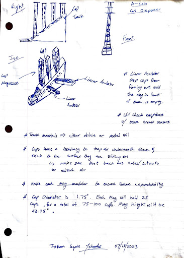
The purpose of this project was to improve upon the current cap dispenser system by reducing its failure rate and increasing the total holding capacity of the dispenser. The issues with the current dispenser included jams caused by an active cap feeder mechanism and a tendency for caps to nest when left in a tower for long periods of time. The re-design of this system targeted these issues in two ways, first by making the entire system passive, allowing gravity to feed the caps into a position where the robot arm could reliably pick up from, and second, by rotating the caps 90 degrees, such that sides of the cap be the contact edge with other caps. This entirely eliminates the issues with nesting, however it comes at the cost of the caps taking more space vertically. The overall goal of this project was to implement these changes to improve the reliability of the system by reducing mechanical complexity and moving parts.
Design Considerations
- Cap Capacity
- 60-100 Caps
- Cap Alignment
- Allow for repeatable robot arm pick ups
- Cap Detection
- Track cap capacity with beam break or infrared sensors
- Passive Cap Feeding
- Reduces Failure Points
- Simplifies programming complexity at the cost of increased mechanical complexity
- 3-D Printable Body
- Allows for rapid iteration
- Reduces part count
- Reduces assembly time
- Modular Design
- Reduces the size of parts to fit on 3-D Printer build plate
- Allows for faster repairs
- Allows for expansion of system to accommodate larger or smaller volumes
Inital Concepts

Prototype & Testing
Failure Mode 1
Failure Mode 2
Failure Mode 1 Solution
Failure Mode 2 Solution
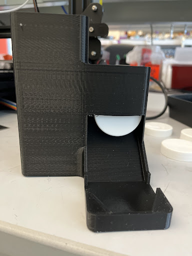
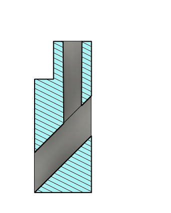
This is the CAD used to eliminate Failure Mode 2. The additional slot reduces friction on the leading edge of the cap, which is what makes the most contact with the ramp floor. If the 3-D printer was able to print finer layers, then this fix would be entirely unnecessary. However, testing showed that gaps within the layers of the printing process caused imperfections which would catch the front edge of the caps as they contact the ramp, causing them to be stuck in place as pictured in Failure Mode 2.
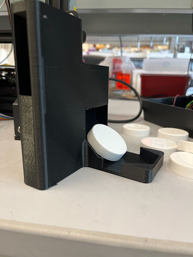
Failure Mode 1 was treated partially by the fix to Failure Mode 2. By increasing the angle of the ramp, this allowed for the caps to gain more speed on their way down the ramp, eliminating this failure.
Final Design
Figure 1
Section View of First Stage, showing the transition between the Cap Magazine and the Main Cap Channel. Shows placement of beam break sensors (Black) and Linear Actuators.
Figure 2
Zoomed in Assembly of the First Stage, showing the Pick Up Platform.
Figure 3
Section View of First Stage, Showing the transition between the Main Cap Channel and the Dispensing Ramp. Shows the placement of beam break sensors (black).
Figure 4
Full Assembly
Figure 5
Shown above is the parametric design of the Pick Up Platform.
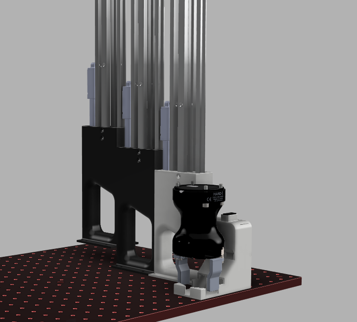
Pictured above is the finalized design of the cap dispenser. The flow of caps is as follows: The system will initially be completely full with caps. The system is designed to hold 70 caps, with 22 held in the magazine, and another 4 in the Main Cap Channel and the Dispensing Ramp. As the robot takes a cap from the Pick Up Platform, the cap behind it will fall forward taking its place, and a cap will fall down from the magazine of the first stage. This will repeat until the first stage magazine is completely depleted. This status will be determined by the black beam break sensors, placed in the transition between the Main Cap Channel and the Dispensing Ramp. Then the linear actuator between the first and second stage will open, releasing the caps from the second stage into the Pick Up Platform. This process will continue until there are no more caps left in the system. The 2nd and 3rd Stages are identical to the first stage with the Dispensing Ramp removed, and are modular, allowing for more stages to be added or removed in the future. Large voids were placed in the structures to optimize 3-D printing speeds and material consumption. The system thus far has a 100% success rate in feeding the caps to the human hand with a sample size of 60 caps being fed through the system. To insure a repeatable pick up point for the robot arm, the Pick Up Platform has 2 angled walls that are designed to tangent to Cap Dispenser with a clearance of .01 inches. The cap behind the cap in Pick Up Platform applies a force on the first cap such that it is perfectly positioned.
Project Delays

The primary delay of the project was due to the need to set up and calibrate the 2 Ender - 3 Pro 3-D Printers, which were used to print the main body of the cap dispenser. The Ender 3 Pro printers need to have their beds leveled and z-height set out of the box, and this process ensures that the printers print a solid first layer. However, these printers also had a firmware that was out of date by 4 years, so the automatic pre-installed functions that normally perform bed leveling and z-height setting were lacking. Additionally, the printers lacked the upgrade that automatically performs these functions. As such, in addition to having to assemble and tune this printers which caused a week delay in the project start, another week was spent on researching methods to update the firmware of the printers, and ordering a CR-Touch, an upgrade that allows the print nozzle of the printer to set the z-height and also construct a height map of the bed. This height map allows the printer to compensate for irregularities in the bed, allowing it to print layers at the perfect distance from the build platform, improving the bed adhesion of the print as well as the consistency of the print layers.
Final CAD
Electronics
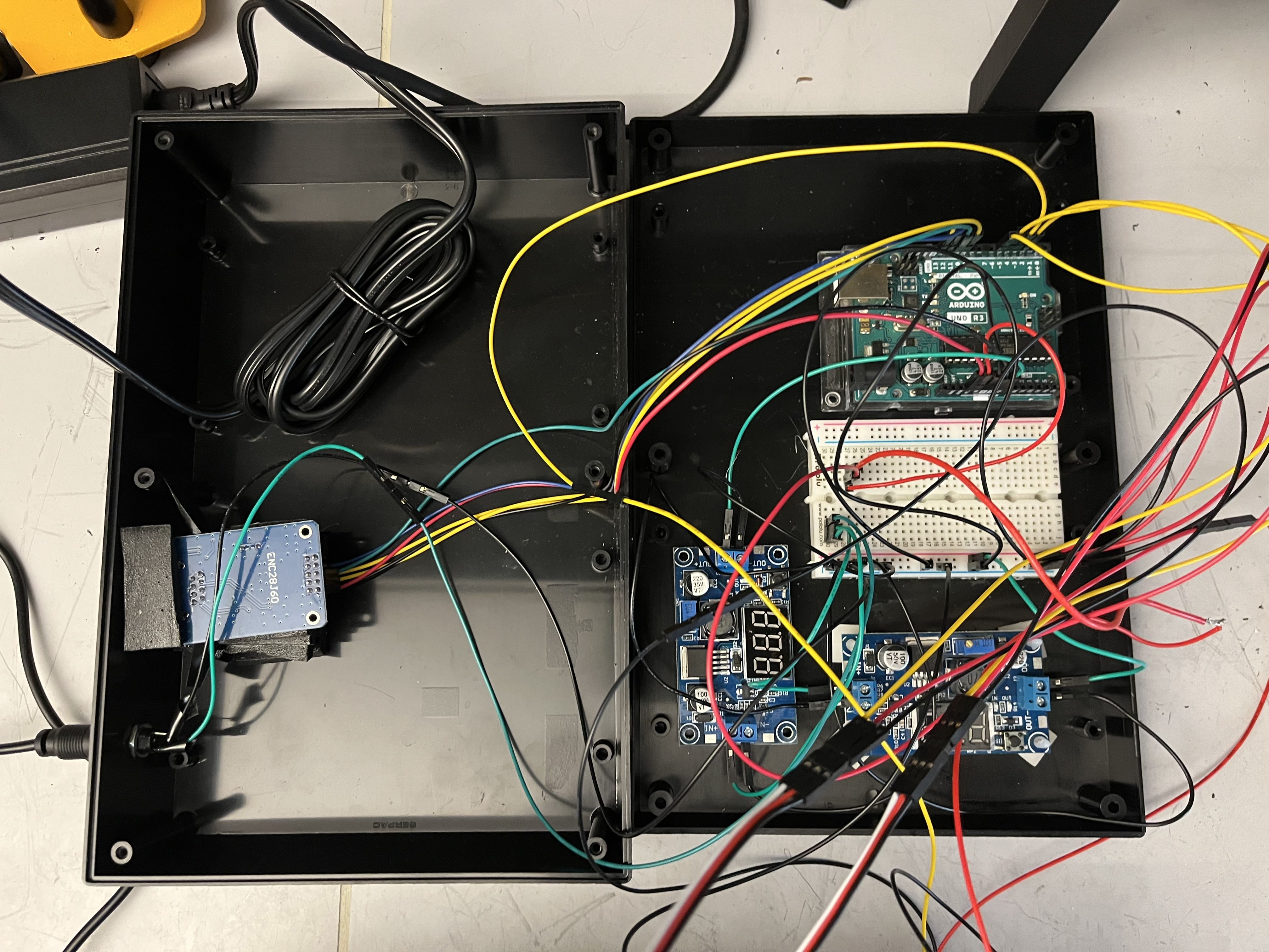
Pictured above is the electrical box that controls the cap dispenser system. The microcontroller in use is an Arduino Uno, which takes 9 volts at its input. The power supply in use provides 12 volts, so a variable voltage regulator is used to downstep the 12 volts to 9 volts. The system makes use of 4 linear actuators, which all require 6 volts at their input. As such, a second voltage regulator is used to downstep the 12 volts of the power supply down to 6 volts. The final electrical component of the cap dispenser is the Ada Fruit Beam Break Sensor, which requires 5 volts of input voltage. This is received directly from the Arduino itself, which has a 5-volt output.
Code
Below is the Arduino Code that runs the Cap Dispenser. The cap dispenser operates passively, using gravity to push caps to the dispensing zone. However, when the first magazine of caps is empty, the beam break sensor at the mouth of the dispenser detects that there is no cap, and opens the next magazine in the system. The system relies on the beam break sensor outputs, which is binary HIGH or LOW value to determine where the cap dispenser need to open. The beam break will output HIGH if the beam is uninterrupted, and will output LOW if the beam is broken, which would be the case if the dispenser is not empty. If the beam is unbroken for 5 seconds, the system will register the dispenser as empty and will open the next magazine of caps. If there is no next magazine of the caps, the system will set the state of the cap dispenser as STOPPED.
  #include <Arduino.h>
  #include <EtherCard.h>
  #include<ArduinoJson.h>
  #include <AceRoutine.h>
  #include <Servo.h>

  using namespace ace_routine;

  // Pin configuration
  const int beamBreakPin = 4;  // Pin for the beam break sensor
  const int actuatorPins[] = {5, 3, 6};  // Pins for the linear actuators

  // Servo objects for controlling the linear actuators
  Servo actuators[3];

  // Variables to track the state of each actuator
  int actuatorStates[] = {0, 0, 0};  // 0: Closed, 1: Open
  int nextOpenActuator = 0;

  // linear actutator open and close value constants
  const int acuClose=1600, acuOpen=1050;

  // Variable to track the start time when the beam is broken
  unsigned long beamBreakStartTime = 0;

  // Duration for which the beam must be continuously broken (in milliseconds)
  const unsigned long beamBreakDuration = 5000;

  //State of Cap Dispenser
  enum State {
    RUNNING,
    STOP
  };

  State state = RUNNING;

  void setup() {
    Serial.begin(9600);

    // Initialize the linear actuators
    for (int i = 0; i < 3; i++) {
      actuators[i].attach(actuatorPins[i]);
      Serial.print("Actuator ");
      Serial.print(i + 1);
      Serial.println(" setup.");
      actuators[i].writeMicroseconds(acuClose);  // Close the actuators initially
    }

    // Initialize the beam break sensor
    pinMode(beamBreakPin, INPUT);
  }

  void loop() {
    if (state == RUNNING) {
      runDispenser();
    }
  }

  void runDispenser() {
    // Check if the beam is connected
    if (digitalRead(beamBreakPin) == HIGH) {
      // Serial.println("HIGH");
      // Beam is connected
      if (beamBreakStartTime == 0) {
        // If this is the first time beam is connected, record the start time
        beamBreakStartTime = millis();
      } else {
        // Check if the beam has been continuously connected for the specified duration
        if (millis() - beamBreakStartTime >= beamBreakDuration) {
          // Beam has been continuously broken for the specified duration
          activateNextActuator();
          // Reset the beam break start time
          beamBreakStartTime = 0;
          delay(2000);
        }
      }
    } else {
      // Beam is broken, reset the start time
      // Serial.println("LOW");
      beamBreakStartTime = 0;
    }
  }

  // Function to activate the next available actuator
  void activateNextActuator() {
    //If last gate is still closed;
    if (nextOpenActuator < 3) {
      if (actuatorStates[nextOpenActuator] == 0) {
        // Actuator is closed, open it
        actuators[nextOpenActuator].writeMicroseconds(acuOpen);
        actuatorStates[nextOpenActuator] = 1;  // Set the state to open

        Serial.print("Actuator ");
        Serial.print(nextOpenActuator + 1);
        Serial.println(" opened.");

        nextOpenActuator++; //Move to next acutator;

        delay(2000); //Wait for actuator to open
      }
    } else {
      // All actuators are open and activateNextActuator is called
      Serial.println("Cap Dispenser is empty");
      state = STOP;
    }
  }
Below is code from the Adafruit website which was used to validate the outputs of the beam break sensor. Source
    /*
    IR Breakbeam sensor demo!
  */

  #define LEDPIN 13
    // Pin 13: Arduino has an LED connected on pin 13
    // Pin 11: Teensy 2.0 has the LED on pin 11
    // Pin  6: Teensy++ 2.0 has the LED on pin 6
    // Pin 13: Teensy 3.0 has the LED on pin 13

  #define SENSORPIN 4

  // variables will change:
  int sensorState = 0, lastState=0;         // variable for reading the pushbutton status

  void setup() {
    // initialize the LED pin as an output:
    pinMode(LEDPIN, OUTPUT);
    // initialize the sensor pin as an input:
    pinMode(SENSORPIN, INPUT);
    digitalWrite(SENSORPIN, HIGH); // turn on the pullup

    Serial.begin(9600);
  }

  void loop(){
    // read the state of the pushbutton value:
    sensorState = digitalRead(SENSORPIN);

    // check if the sensor beam is broken
    // if it is, the sensorState is LOW:
    if (sensorState == LOW) {
      // turn LED on:
      digitalWrite(LEDPIN, HIGH);
    }
    else {
      // turn LED off:
      digitalWrite(LEDPIN, LOW);
    }

    if (sensorState && !lastState) {
      Serial.println("Unbroken");
    }
    if (!sensorState && lastState) {
      Serial.println("Broken");
    }

    lastState = sensorState;
  }

